Battery positioning clamp

A technology for positioning fixtures and batteries, which is applied in manufacturing tools, auxiliary devices, auxiliary welding equipment, etc., and can solve problems such as yield reduction and scratching of batteries.

Pending Publication Date: 2021-01-01
WUXI LEAD INTELLIGENT EQUIP CO LTD
View PDF0 Cites 2 Cited by
  • Summary
  • Abstract
  • Description
  • Claims
  • Application Information

AI Technical Summary

Problems solved by technology

[0004] Based on this, it is necessary to address the problem that in the process of positioning and clamping the battery by the clamp in the prior art, the battery is in contact with the clamping ass

Method used


Image

  • Battery positioning clamp
  • Battery positioning clamp
  • Battery positioning clamp

Examples


Embodiment Construction

[0040] In order to make the above objects, features and advantages of the present invention more comprehensible, specific implementations of the present invention will be described in detail below in conjunction with the accompanying drawings. In the following description, numerous specific details are set forth in order to provide a thorough understanding of the present invention. However, the present invention can be implemented in many other ways different from those described here, and those skilled in the art can make similar improvements without departing from the connotation of the present invention, so the present invention is not limited by the specific embodiments disclosed below.

[0041] In describing the present invention, it should be understood that the terms "center", "longitudinal", "transverse", "length", "width", "thickness", "upper", "lower", "front", " Back", "Left", "Right", "Vertical", "Horizontal", "Top", "Bottom", "Inner", "Outer", "Clockwise", "Counte...


PUM


Abstract

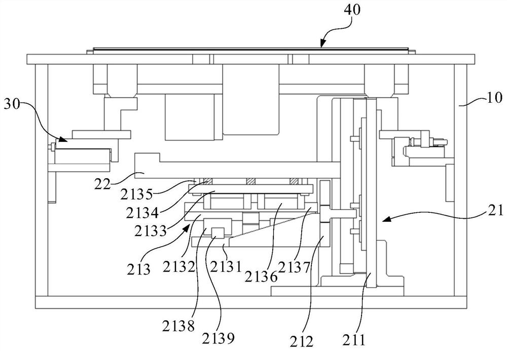
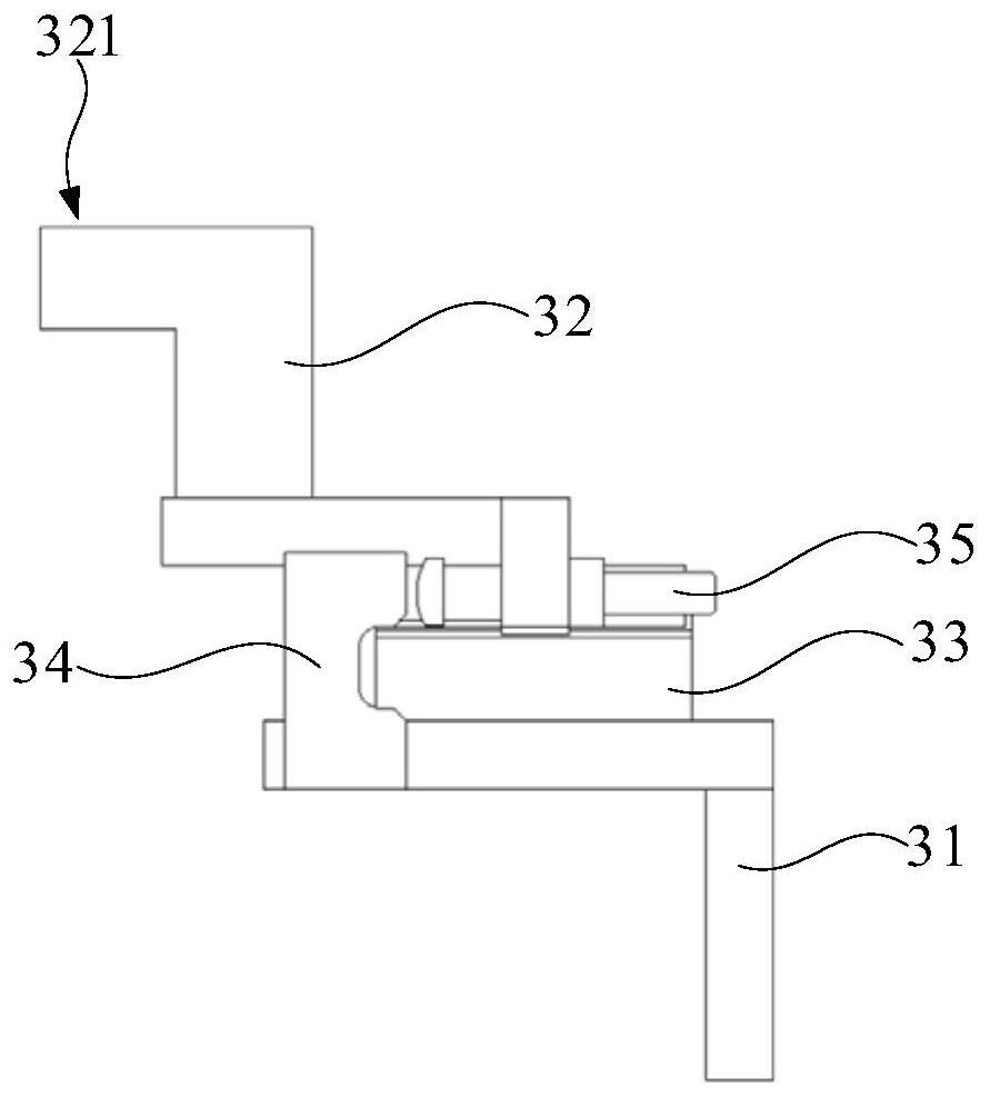
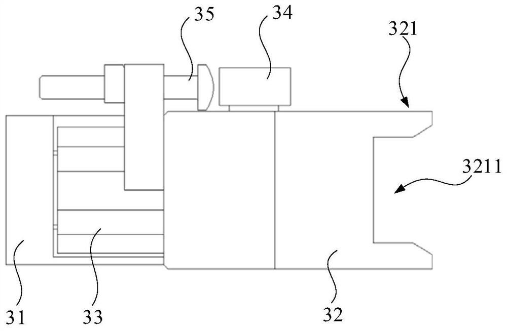
The invention relates to a battery positioning clamp. The battery positioning clamp comprises a bearing assembly, guide assemblies and a clamping assembly, wherein the bearing assembly comprises a supporting mechanism and a bearing plate arranged at the supporting mechanism; the supporting mechanism is used for driving the bearing plate to move in a first direction and the bearing plate is used for bearing a battery; the bearing assembly is uniformly distributed with the guide assemblies at the two sides of a second direction perpendicular to the first direction; the guide assemblies are in contact with the two sides, in the second direction, of the battery borne on the bearing plate; the clamping assembly is arranged at one side of the first direction of the bearing assembly, and is provided with a clamping position for clamping the battery; and while the bearing plate moves in the first direction, the battery can be driven to enter the clamping position.

Description

technical field [0001] The invention relates to the technical field of battery manufacturing, in particular to a battery positioning jig. Background technique [0002] In the battery manufacturing process, it is often necessary to use a jig to clamp and position the battery, and then process the battery. For example, in the process of welding the top cover on a prismatic battery, it is first necessary to put the battery into the jig, and use the clamping assembly of the jig to clamp the battery, and then the clamping assembly releases the battery, but keeps the clamping assembly in contact with the battery status. Then, the battery is lifted to a specified height, and the battery is guided by the clamping assembly during the lifting process of the battery. Finally, the clamping assembly clamps the battery to realize the positioning and clamping of the battery. [0003] It can be seen that in the process of positioning and clamping the battery with the traditional clamp, t...

Claims


Application Information

Patent Timeline
IPC IPC(8): B23K37/04B23K101/36
CPCB23K37/0443B23K2101/36
Inventor 不公告发明人
Owner WUXI LEAD INTELLIGENT EQUIP CO LTD
Why Eureka
Try Eureka