
Garbage sanitation vehicle with lifting function

A technology for sanitation vehicles and garbage, applied in the field of garbage sanitation vehicles, can solve the problems of human injury, high labor intensity, and many labors, and achieve the effects of avoiding high-intensity operations, reducing labor costs, and high safety.

Inactive Publication Date: 2021-01-01
仙居度晓科技有限公司
View PDF0 Cites 1 Cited by
  • Summary
  • Abstract
  • Description
  • Claims
  • Application Information

AI Technical Summary

Problems solved by technology

[0002] Cranes refer to multi-action hoisting machinery that vertically lifts and horizontally transports heavy objects within a certain range. Hoisting machinery is widely used and has a large number. It greatly reduces people's labor intensity, improves labor efficiency, and improves the quality of workers. It has an indelible contribution to the realization of industrial modernization and automation, but if it is not properly used and managed, it is also very easy to cause personal and equipment accidents, causing serious injuries to people.
[0003] Hoisting machinery also has a certain application prospect on garbage sanitation vehicles. When traditional garbage sanitation vehicles transport garbage cans full of garbage, sanitation workers usually pull the garbage cans onto the vehicle. The workers consume more labor and the labor intensity is high. It is easy to threaten the life safety of sanitation workers, and at the same time, it is inefficient to manually carry garbage bins. At present, there is a lack of a garbage sanitation vehicle using lifting machinery. The invention is a garbage sanitation vehicle with a lifting function.

Method used


Image

  • Garbage sanitation vehicle with lifting function
  • Garbage sanitation vehicle with lifting function
  • Garbage sanitation vehicle with lifting function

Examples


Embodiment Construction

[0017] Combine below Figure 1 to Figure 7 The present invention is described in detail, for the convenience of description, the orientations mentioned below are now specified as follows: figure 1 The projection relationship of itself is the same as the up, down, left, right, front, and rear directions.

[0018] The present invention relates to a garbage sanitation vehicle with a lifting function, which is mainly applied to the garbage sanitation vehicle. The invention will be further described below with reference to the accompanying drawings of the present invention.

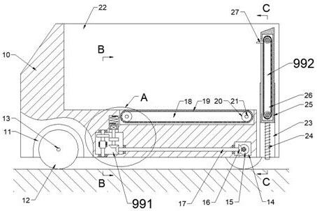
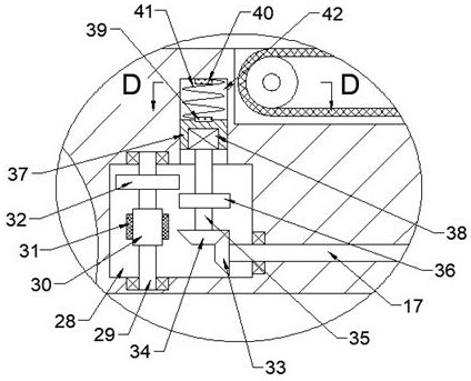
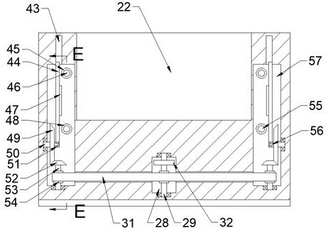
[0019]A garbage sanitation vehicle with a lifting function of the present invention includes a vehicle body 10, and a wheel 12 is rotatably provided on the lower side of the vehicle body 10. When the wheel 12 rotates, the vehicle body 10 can be driven on the ground. After the car body 10 moves to the designated position, the lifting device 991 provided in the car body 10 can lower the lifting plate 25 provide...


PUM


Abstract

The invention relates to the related field of cranes, in particular to a garbage sanitation vehicle with a lifting function. The garbage sanitation vehicle comprises a vehicle body, wheels are rotatably arranged on the lower side of the vehicle body, and the vehicle body can be driven to move on the ground when the wheels rotate; after the vehicle body moves to a designated position, a lifting device arranged in the vehicle body can lower a lifting plate arranged on the right side of the vehicle body, and workers can conveniently place a garbage can on the lifting plate; the lifting device comprises a garbage carrying cavity arranged at an upward opening and a rightward opening in the end wall of the upper side of the vehicle body, a lifting cavity penetrating through the bottom wall of the garbage carrying cavity is formed at a rightward opening in the end wall of the lower side of the garbage carrying cavity; a baffle behind the vehicle can be lowered, the baffle can automatically lift the garbage can after the workers place the garbage can on the baffle, the baffle can automatically move the garbage can into the vehicle after lifting the garbage can to a certain height, high-intensity operation of the workers is avoided, and the labor cost is reduced; and mechanical transmission operation is adopted in the whole process, and the efficiency is high.

Description

technical field [0001] The invention relates to the related field of cranes, in particular to a garbage sanitation vehicle with a lifting function. Background technique [0002] Crane refers to a multi-action hoisting machine that vertically lifts and horizontally transports heavy objects within a certain range. The lifting machine is widely used and has a large number. It greatly reduces people's labor intensity, improves labor efficiency, and improves staff. It has an indelible contribution to the realization of industrial modernization and automation, but if it is used improperly, it is also prone to personal and equipment accidents, causing serious harm to people. [0003] Lifting machinery also has certain application prospects in garbage sanitation trucks. When traditional garbage sanitation trucks transport garbage cans full of garbage, sanitation workers usually pull the garbage cans to the truck. The workers consume more labor and are labor-intensive. It is easy to...

Claims


Application Information

Patent Timeline
Patent Type & Authority Applications(China)
IPC IPC(8): B65F3/08
CPCB65F3/08
Inventor 许光痕
Owner 仙居度晓科技有限公司
Learn More