
A central feeding device and method for silica particle deposition

A silicon dioxide and feeding device technology, which is applied in the direction of measuring devices, general control systems, sequence/logic controller program control, etc., can solve the problems of low utilization rate of land resources, frequent operations by operators, and heavy physical exertion, etc. problems, to achieve the effect of improving feeding quality and work efficiency, reducing the risk of human error, and high-quality and stable feeding

Active Publication Date: 2019-06-25
YANGTZE OPTICAL FIBRE & CABLE CO LTD
View PDF5 Cites 0 Cited by
  • Summary
  • Abstract
  • Description
  • Claims
  • Application Information

AI Technical Summary

Problems solved by technology

Operators operate frequently, consume a lot of physical strength, and work efficiency is low
The risk of human error increases dramatically as working hours and intensity increase
[0004] (2) In the single-line silicon dioxide particle loose rod deposition feeding mode, the operator needs to frequently open the upper cover of the large material tank during the process of pouring the barreled raw materials into the buffer tank to remove impurities such as air and sweat. If the material is mixed into the raw material, the raw material will be impure, and the bubble content in the feed liquid will increase, which will greatly affect the deposition quality of silica particles and reduce the normal production efficiency of the equipment.
However, due to the repeated opening of the centralized material tank, the problems of impure raw materials and high bubble content as mentioned in the second point still exist
Moreover, in this mode, once any failure of the centralized tank requires maintenance, all deposition lines have a greater risk of shutdown
Moreover, this centralized material tank has a large volume, occupies a large area, and has a low utilization rate of land resources.

Method used


Image

  • A central feeding device and method for silica particle deposition
  • A central feeding device and method for silica particle deposition

Examples


Embodiment Construction

[0023] In order to better understand the present invention, the present invention will be further described below in conjunction with the accompanying drawings and embodiments.

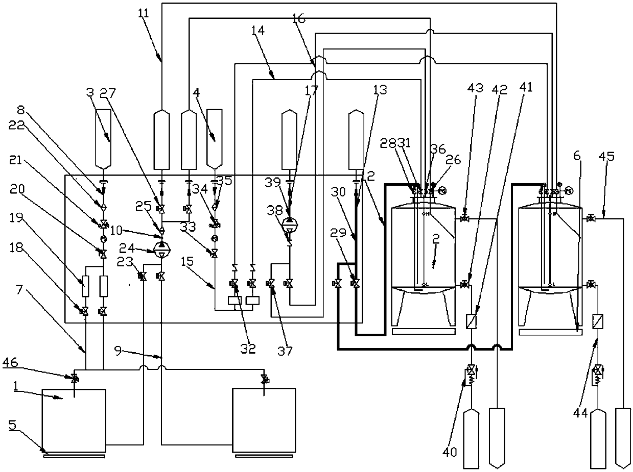
[0024] Such as figure 1As shown, a central feeding device for the deposition of silica particles includes several raw material tanks 1, several buffer tanks 2, stabilized gas tanks 3 and pressure gas tanks 4, and several raw material tanks are equipped with The air supply port and the filling port, the air supply port is connected to one end of the air supply main pipe 8 through the air supply branch pipe 7, the stabilized air tank is connected to the other end of the air supply main pipe, and the filling port is connected to the filling main pipe 10 through the filling pipe 9 , Several buffer tanks are provided with feed inlet, feed inlet, air inlet and exhaust outlet, the feed inlet is connected with the filling main pipe through the feed sub-pipe 11, and the feed port is connected with the feed mai...

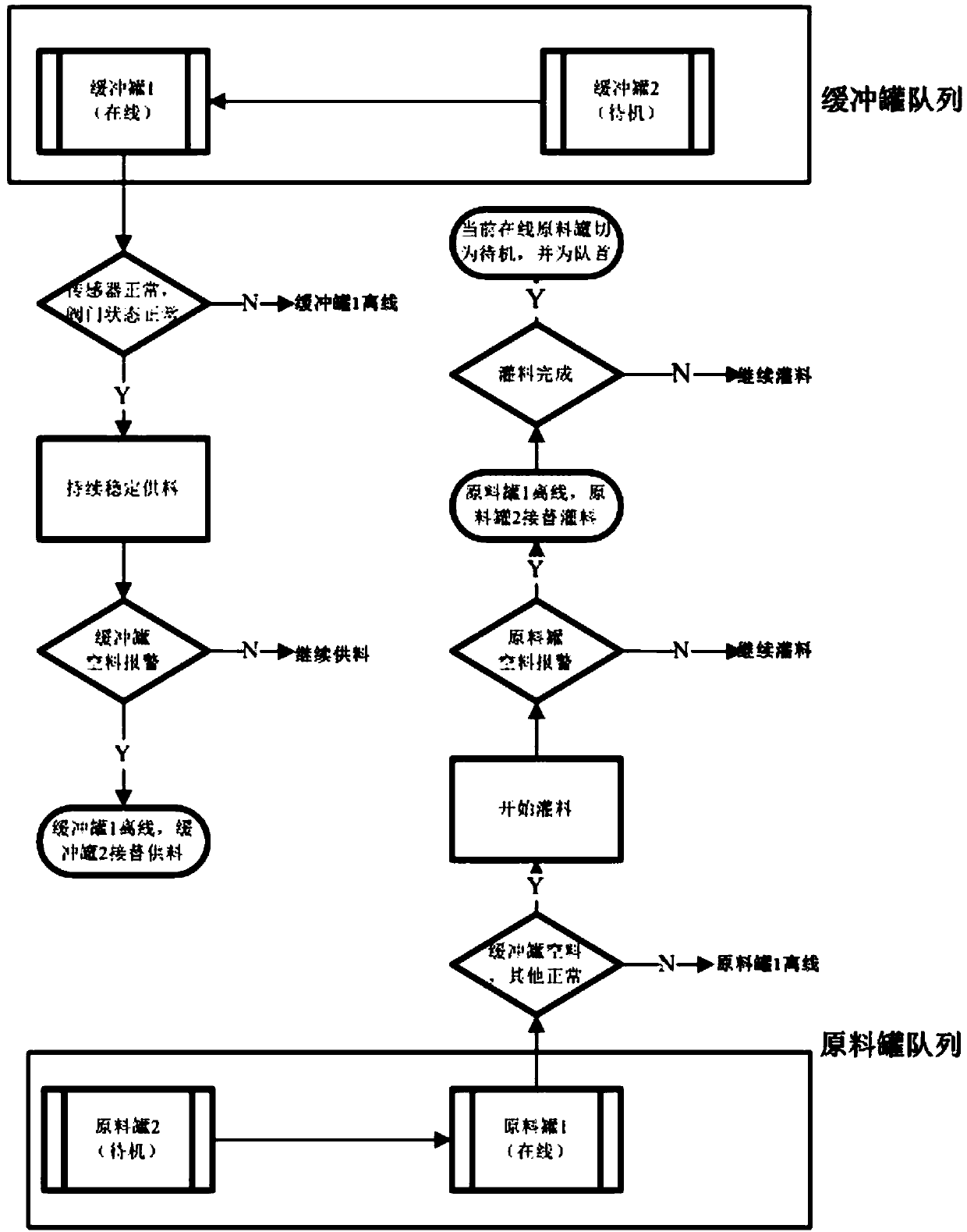

PUM


Abstract

The invention provides a central feeding device and a central feeding method for deposition of silicon dioxide particles. The central feeding device comprises a plurality of raw material tanks, a plurality of buffer tanks, a pressure-stabilizing gas tank and a material pressing gas tank, wherein each of the plurality of raw material tanks is provided with a gas supplementing port and a material filling port, each gas supplementing port is connected with one end of a gas supplementing main pipe through a gas supplementing branch pipe, the pressure-stabilizing gas tank is connected with the other end of the gas supplementing main pipe, each material filling port is connected with a material filling main pipe through a material filling branch pipe, each of the plurality of buffer tanks is provided with a material inlet, a material feeding port, a gas inlet and a gas exhaust port, each material inlet is connected with the material filling main pipe through a material inlet branch pipe, each material feeding port is connected with one end of a material feeding main pipe through a material feeding branch pipe, the other end of the material feeding main pipe is connected with a deposition production line, each gas inlet is connected with one end of a gas inlet main pipe through a gas inlet branch pipe, the other end of the gas inlet main pipe is connected with the material pressing gas tank, each gas exhaust port is connected with one end of a gas exhaust main pipe through a gas exhaust branch pipe, and the other end of the gas exhaust main pipe is connected with a main gas exhaust port. The central feeding device and the central feeding method have the advantages of being high in degree of automation, achieving continuous operation and being high in efficiency.

Description

technical field [0001] The invention belongs to the technical field of silicon dioxide particle loose rod deposition, and in particular relates to a central feeding device and method for silicon dioxide particle deposition. Background technique [0002] In recent years, with the continuous development of communication technology 4G and 5G, the demand for faster Internet access by the public worldwide is increasing, the upgrading of communication bandwidth of each main branch is accelerating, and the rapid development of the optical fiber and cable industry is also promoting the development of optical fiber manufacturing technology. keep improve. The technology of manufacturing optical fiber preforms by deposition outside the tube has also been applied by more and more optical fiber suppliers. In the preform manufacturing process, the deposition of loose rods of silica particles is the basis and one of the keys for the production of high-quality optical fibers. In the deposi...

Claims


Application Information

Patent Timeline
Patent Type & Authority Patents(China)
IPC IPC(8): G05B19/05G01D21/02
CPCG01D21/02G05B19/054
Inventor 王志勇张华明王瑞春顾立新刘善沛罗军高则尚朱方龙杨轶
Owner YANGTZE OPTICAL FIBRE & CABLE CO LTD
Learn More