Foundation pit supporting structure and method

A foundation pit support and foundation pit technology, which is applied in foundation structure engineering, excavation, construction, etc., can solve problems such as foundation pit instability, lack of further utilization of structure and soil interaction, and achieve the effect of structural safety.

Active Publication Date: 2021-01-01
JINAN MUNICIPAL ENG DESIGN & RES INSITITUTE GRP
View PDF6 Cites 0 Cited by
  • Summary
  • Abstract
  • Description
  • Claims
  • Application Information

AI Technical Summary

Problems solved by technology

[0003] The inventors have learned that the force-bearing forms of these retaining structures rely on their own strength to resist the lateral force of the soil, and their supporting capacity depends on the strength of the structure itself, especially the cantilever structure, but for structures and soil The interaction is not further exploited
In addition, in the foundation pit project, the drainage system needs to be set up separately. In case of heavy rain or drainage failure, accidents such as foundation pit instability are prone to occur

Method used


Image

  • Foundation pit supporting structure and method
  • Foundation pit supporting structure and method
  • Foundation pit supporting structure and method

Examples


Embodiment 1

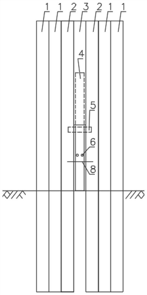
[0023] like Figure 1-Figure 6 As shown, this embodiment provides a foundation pit support structure, which includes a plurality of pile rows whose lower ends can be inserted into the soil layer below the foundation pit. The pile rows are composed of a plurality of pipe piles arranged vertically. The connecting plate 3 is fixed so that a plurality of piles are arranged in rows; a gap is formed between the lower end of the connecting plate 3 and the bottom surface of the foundation pit, and a rotating rod 4 is installed on the upper part of the gap, and one end of the rotating rod 4 can extend into the foundation pit. An unloading platform is formed in the soil layer of the side wall of the pit, and a fixed notch 6 is provided between the other end and the upper end of the pile row to fix the diagonal bracing member 7 to transmit the moment.

[0024] Specifically, in this embodiment, the two pipe piles close to the diagonal bracing member 7 need to bear the reaction force provi...

Embodiment 2

[0038] The present embodiment provides a method for foundation pit support, comprising the following steps:

[0039] Before the excavation of the foundation pit, sink the foundation pit support structure as a whole into the stratum to a set depth;

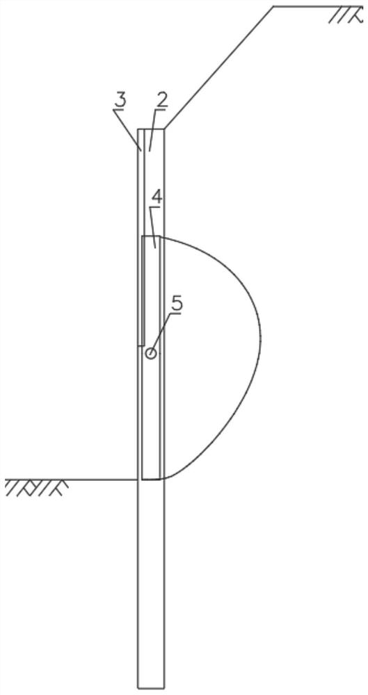
[0040] After the foundation pit is excavated to the base, make the lower end of the rotating rod 4 flush with the bottom surface of the foundation pit, and use auxiliary driving equipment to push the lower end of the rotating rod 4 to rotate towards the side wall of the foundation pit to perform rotary excavation. When rotating 90° , stop rotating;

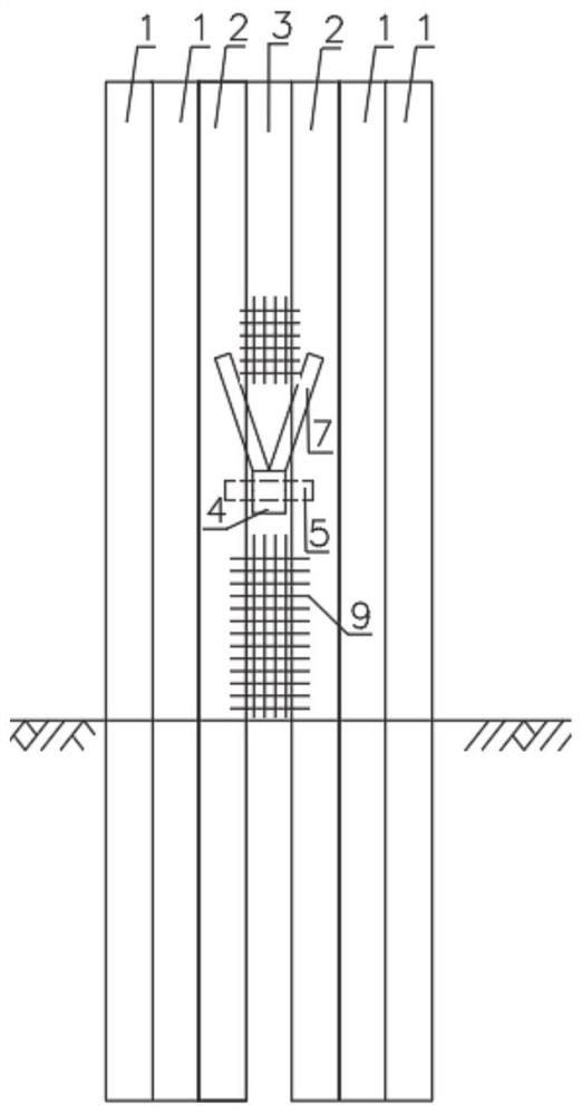
[0041] Utilize the diagonal bracing member 7 to support between the end of the rotating rod 4 away from the side wall of the foundation pit and the upper end side of the adjacent pipe pile away from the side wall of the foundation pit;

[0042] Removal of constraints on auxiliary drive equipment.

[0043] The overall sinking depth of the foundation pit supporting structure is set as fo...


PUM


Abstract

The invention relates to a foundation pit supporting structure and method. The foundation pit supporting structure comprises a plurality of pile rows, wherein the lower ends of the pile rows can be inserted into a soil layer below a foundation pit, each pile row is composed of a plurality of tubular piles which are vertically arranged side by side, and every two adjacent pile rows are fixed through a vertical connecting plate so as to arrange the plurality of pile rows in rows; and a notch is formed between the lower end of the connecting plate and the bottom surface of the foundation pit, a rotating rod is rotationally arranged on the upper portion of the notch, one end of the rotating rod can extend into the soil layer on the side wall of the foundation pit to form an unloading platform,and an inclined strut component is arranged between the other end of the rotating rod and the upper ends of the pile rows to transmit torque.

Description

technical field [0001] The disclosure belongs to the technical field of foundation pit support, and in particular relates to a foundation pit support structure and method. Background technique [0002] In foundation pit engineering, the most common support method is to use support structures, such as anchor support structures, support support structures and cantilever support structures. [0003] The inventors have learned that the force-bearing forms of these retaining structures rely on their own strength to resist the lateral force of the soil, and their supporting capacity depends on the strength of the structure itself, especially the cantilever structure, but for structures and soil The interaction was not exploited further. In addition, in the foundation pit project, the drainage system needs to be set up separately. In case of heavy rain or drainage failure, accidents such as foundation pit instability are prone to occur. Contents of the invention [0004] The pu...

Claims


Application Information

Patent Timeline
Patent Type & Authority Applications(China)
IPC IPC(8): E02D17/04
CPCE02D17/04
Inventor 马正匡伟张光利蔡仕强张永康王胜华
Owner JINAN MUNICIPAL ENG DESIGN & RES INSITITUTE GRP
Why Eureka
Try Eureka