
Load-reducing and height-increasing structure of existing retaining wall and its construction method

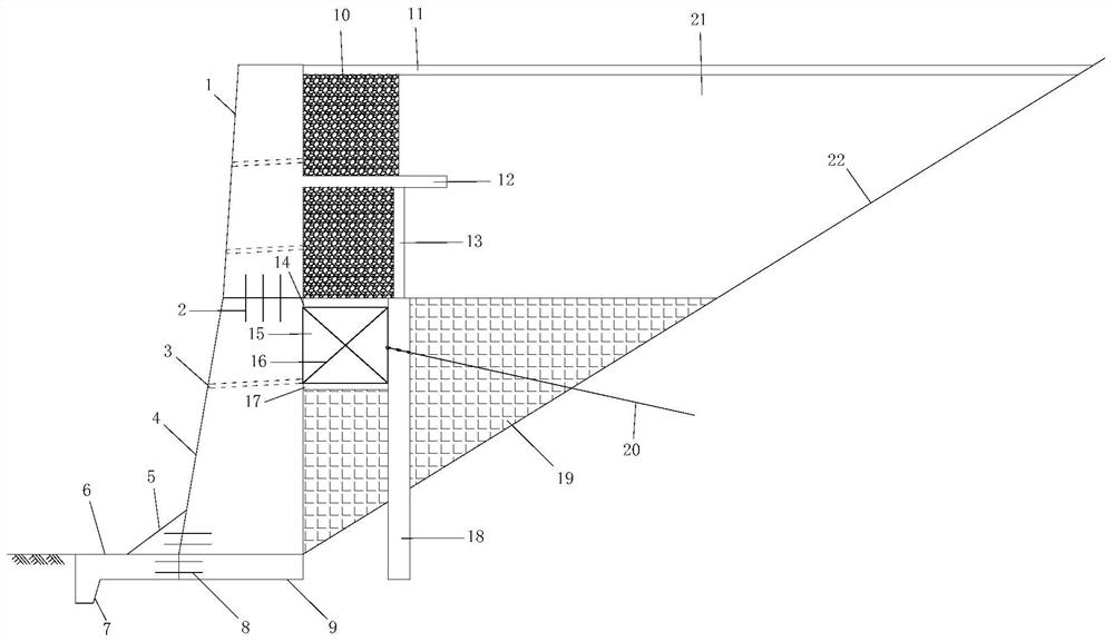
A construction method and retaining wall technology, applied in the direction of basic structure engineering, underwater structures, foundation structure repair, etc., can solve problems such as limited bearing capacity, high soil pressure, hidden safety hazards, etc., to achieve enhanced horizontal bearing capacity, The effect of increasing the vertical bearing capacity and increasing the safety factor

Active Publication Date: 2021-07-13
ANHUI HIGHWAY ENG CORP
View PDF0 Cites 0 Cited by
  • Summary
  • Abstract
  • Description
  • Claims
  • Application Information

AI Technical Summary

Problems solved by technology

With the progress of bulldozing and filling construction in the project, the height of the soil increases, and the safety and stability of the existing retaining wall cannot meet the current requirements. Heightened and reinforced
However, the project of demolishing and rebuilding the existing retaining wall has the problems of large amount of work, labor and time. At the same time, in the process of demolishing the existing retaining wall, the original slope is prone to instability and there is a certain risk
In addition, there are still some problems in the existing related technologies and attempts of heightening and strengthening the existing retaining wall: for example, the bearing capacity of the existing retaining wall after heightening and strengthening is limited, resulting in high soil pressure; the effect of traditional unloading slabs Poor, resulting in excessive settlement of the original foundation, bringing safety hazards

Method used


Image

  • Load-reducing and height-increasing structure of existing retaining wall and its construction method
  • Load-reducing and height-increasing structure of existing retaining wall and its construction method
  • Load-reducing and height-increasing structure of existing retaining wall and its construction method

Examples


Embodiment Construction

[0030] The following will clearly and completely describe the technical solutions in the embodiments of the present invention with reference to the accompanying drawings in the embodiments of the present invention. Obviously, the described embodiments are only some, not all, embodiments of the present invention. All other embodiments obtained by persons of ordinary skill in the art based on the embodiments of the present invention belong to the protection scope of the present invention.

[0031] Those skilled in the art should understand that in the disclosure of the present invention, the terms "vertical", "transverse", "upper", "lower", "front", "rear", "left", "right", " The orientation or positional relationship indicated by "vertical", "horizontal", "top", "bottom", "inner", "outer", etc. is based on the orientation or positional relationship shown in the drawings, which are only for the convenience of describing the present invention and The above terms should not be con...


PUM


Abstract

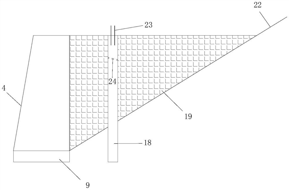
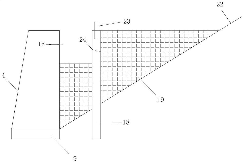
The invention provides a load reduction and heightening structure of an existing retaining wall and a construction method thereof. At a horizontal clear distance of one-third of the height from the back of the existing retaining wall, the construction of the lead-hole type prefabricated sheet pile is carried out. Excavate the foundation trench at the upper part between the existing retaining wall and the prefabricated sheet pile, set a reinforcement layer at the bottom of the foundation trench and hang and set a bracket on the reinforcement layer, place the top plate on the bracket, and add a foundation outside the original foundation of the existing retaining wall Expand the foundation and connect it through horizontal connecting ribs. The outer side of the expanded foundation is provided with an extension wall toe, and ribs are added on the upper part. The ribs and the bottom of the existing retaining wall are provided with horizontal connecting ribs. At the top of the retaining wall, set a super-long unloading plate in the middle of the heightened retaining wall, set drain holes in sequence below the super-long unloading plate of the heightened retaining wall, and finally set a water filter layer and Artificially fill the soil, and set a surface layer on the top of the filter layer and the artificial filling soil, and the top of the surface layer is at the same height as the top of the heightened retaining wall.

Description

technical field [0001] The invention relates to the field of retaining wall construction, in particular to a load reduction and heightening structure of an existing retaining wall and a construction method thereof. Background technique [0002] A retaining wall is a structure that supports roadbed fill or hillside soil and prevents the deformation and instability of the fill or soil. It is widely used in housing construction, highways, railways, mines, water conservancy and other projects. With the progress of bulldozing and filling construction in the project, the height of the soil increases, and the safety and stability of the existing retaining wall cannot meet the current requirements. Heightened and reinforced. However, the project of demolishing and rebuilding the existing retaining wall has the problems of large amount of work, labor and time. At the same time, in the process of demolishing the existing retaining wall, the original slope is prone to instability and ...

Claims


Application Information

Patent Timeline
Patent Type & Authority Patents(China)
IPC IPC(8): E02D37/00E02D29/02E02D3/10
CPCE02D3/10E02D29/02E02D29/0233E02D29/0283E02D37/00E02D2250/0023
Inventor 夏永红孟平丛王清峰宇汝平邹小乐许琼单洁郭鹏王志涛光青元陈彬彭进朝宋长莉徐盈飞
Owner ANHUI HIGHWAY ENG CORP
Learn More