Assembly type handrail supporting rod structure
A support rod and prefabricated technology, used in fences, building types, buildings, etc., can solve the problems of inconvenient installation and inability to adjust flexibly, and achieve the effect of simple structure installation, convenient later maintenance, and improved anti-deformation ability.
- Summary
- Abstract
- Description
- Claims
- Application Information
AI Technical Summary
Problems solved by technology
Method used
Image
Examples
Embodiment 1
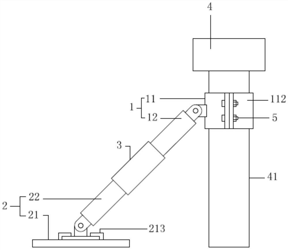
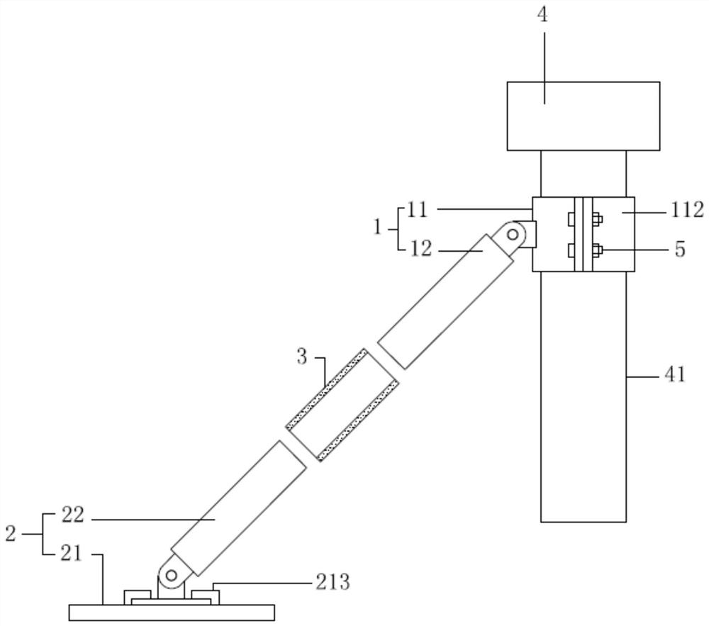
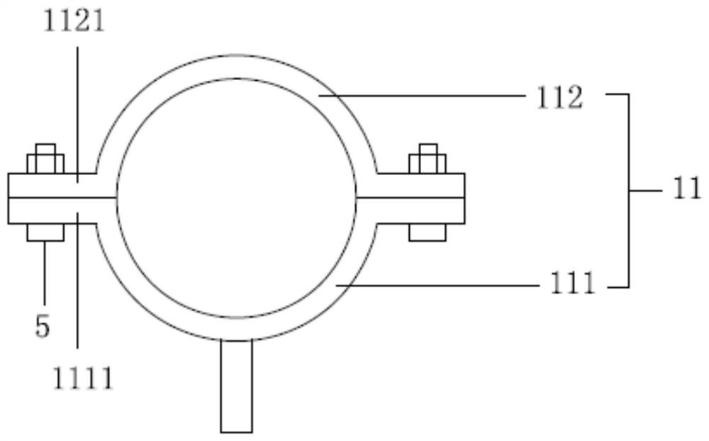
[0022] see Figure 1 to Figure 4 , the figure shows an assembled railing support structure provided by Embodiment 1 of the present invention, including a first support unit 1, a second support unit 2 and a combined sleeve 3, and the first support unit 1 includes a connecting sleeve 11 and The first support rod 12, the connection sleeve 11 is set on the column 41 of the railing 4, the first support rod 12 is hinged on the connection sleeve 11, the surface of the first support rod 12 is provided with threads, and the combined sleeve 3 is connected by threads on the second On a support rod 12, the second support unit 2 includes a base 21 and a second support rod 22, the base 21 is fixedly installed on the ground, the second support rod 22 is hinged on the base 21, and the combined sleeve 3 is threaded on the second on the support rod 22.
[0023] Specifically, see Figure 1 to Figure 4 , the connecting sleeve 11 includes a first arc-shaped plate 111 and a second arc-shaped plat...
Embodiment 2
[0029] see Figure 1 to Figure 4 , the figure shows an assembled railing support structure provided by Embodiment 2 of the present invention. On the basis of the above embodiments, this embodiment further makes the following technical solutions as improvements: the base 21 includes a bottom plate 211 And the hinged seat 212, the bottom plate 211 is fixedly installed on the ground, the hinged seat 212 is detachably installed on the bottom plate 211, the second support rod 22 is hinged on the hinged seat 212; the bottom plate 211 is provided with two baffles 213 symmetrically arranged , the cross section of the baffle 213 is "L" shape, and the hinged seat 212 is slidably connected between the two baffles 213 .
[0030] The hinged seat on the base is slidably connected between the two baffles, the baffle is perpendicular to the second support rod, and the sliding direction of the hinged seat is perpendicular to the second support rod, so the support to the column will not be affe...
Embodiment 3
[0032] see Figure 1 to Figure 4 , the figure shows an assembled railing support rod structure provided by Embodiment 3 of the present invention. On the basis of the above embodiment, this embodiment further makes the following technical solutions as improvements: the combined casing 3 The length is less than the length of the first support rod 12 .
[0033] The length of the combined sleeve is less than the length of the first support rod, so as to avoid the situation that when the first support rod and the second support rod are coaxially arranged, the ends of the two are pressed together. At this time, if the length of the combined sleeve is greater than the first The length of the support rod, the combined sleeve will not be able to thread the second support rod.
PUM
 Abstract
Description
Claims
Application Information
 - R&D
- Intellectual Property
- Life Sciences
- Materials
- Tech Scout
- Unparalleled Data Quality
- Higher Quality Content
- 60% Fewer Hallucinations
Browse by: Latest US Patents, China's latest patents, Technical Efficacy Thesaurus, Application Domain, Technology Topic, Popular Technical Reports.
© 2025 PatSnap. All rights reserved.Legal|Privacy policy|Modern Slavery Act Transparency Statement|Sitemap|About US| Contact US: help@patsnap.com


