High-performance wiring terminal strip

A terminal block, high-performance technology, applied in the direction of connection, conductive connection, clamping/spring connection, etc., can solve the problems that affect the accuracy of test data, the test probe has no stable force point, and the data stability is poor. To achieve the effect of improving convenience, ensuring reliability and improving accuracy

Pending Publication Date: 2022-02-25
镇江宏联电工有限公司
View PDF3 Cites 0 Cited by
  • Summary
  • Abstract
  • Description
  • Claims
  • Application Information

AI Technical Summary

Problems solved by technology

[0007] After the product is installed, it is necessary to test the performance of the product. However, due to the structural design problems of all existing types of terminals, the test probe does not have a stable stress point during the test. Therefore, it needs to be placed on the metal conductive sheet of the product. Hold the test probe with your hands to test, this test method is greatly affected by human factors, and the data stability is poor, which affects the test accuracy and the accuracy of the test data

Method used


Image

  • High-performance wiring terminal strip
  • High-performance wiring terminal strip
  • High-performance wiring terminal strip

Examples


Embodiment 1

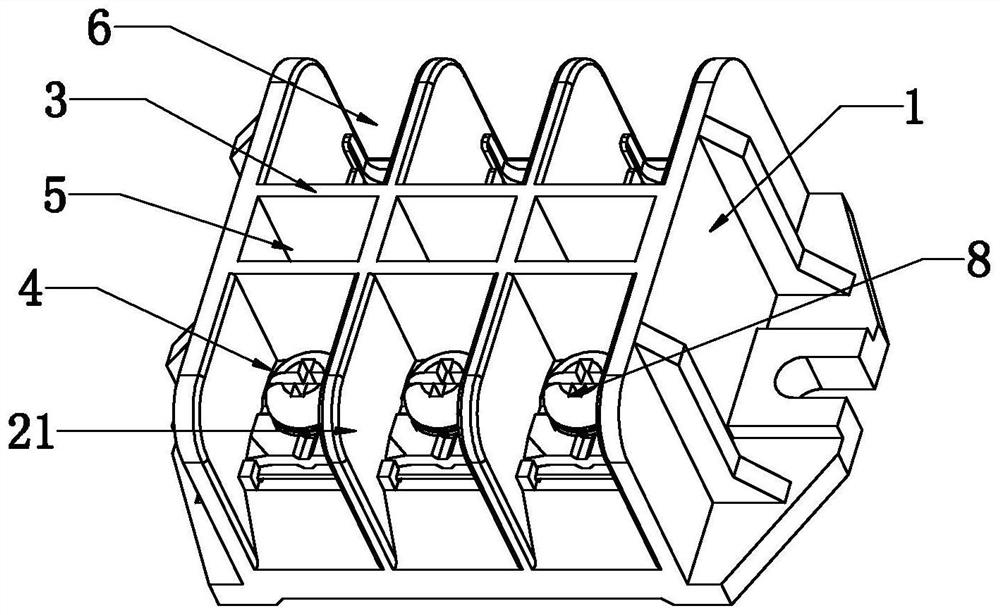
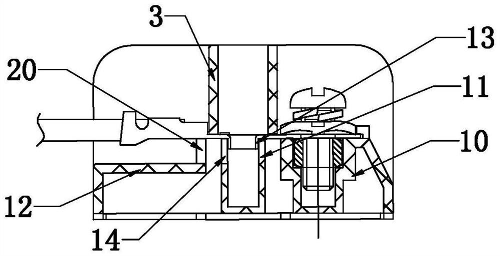
[0037]The high-performance wiring terminal block of this embodiment is illustrated by taking a single-phase wiring unit as an example. It includes an insulating base 1 and a metal conductive sheet 2 that can be placed in the insulating base for connecting wires. The base 1 includes a bottom plate and two side plates on the bottom plate, and a support spacer between the two side plates is provided on the base, wherein the support spacer can adopt an integrated multi-cavity structure or multiple Independent structure, said supporting spacer in the present embodiment is preferably a front fixed seat 10, an insulating shell 11 as a detection well and a rear support seat 12 arranged in the insulating base 1, through the front fixed seat 10, The insulating shell 11 and the rear support seat 12 can support the metal conductive sheet and divide the metal conductive sheet into three parts for isolation. Two transverse partitions 3 are also arranged between the two side plates of the ins...

Embodiment 2

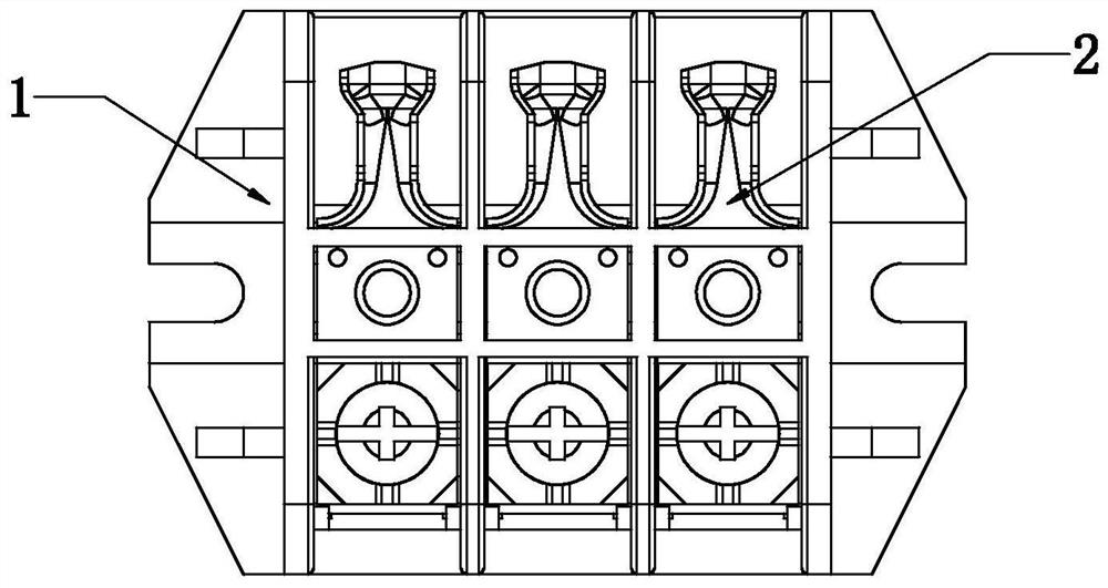
[0040] The high-performance terminal block of this embodiment is a kind of Figure 1-7 The terminal block of the three-phase connection unit shown in the figure can be seen from the figure that the high-performance terminal block of this embodiment is actually composed of multiple phase connection units assembled on the same insulating base, and the left and right sides of the insulating base The side is provided with a U-shaped groove ( figure 2 The direction shown), the specific structure of each single-phase wiring unit is the same as that of Embodiment 1, specifically, between the two side plates of the insulating base 1, there are two The longitudinal partition 21 vertically penetrates from the upper part of the insulating base (the top is flush with the transverse partition) to the bottom of the insulating base, so that three metal conductive sheets can be installed to form three wiring units, Depend on figure 2 It can be seen that two horizontal partitions and two v...


PUM


Abstract

The invention discloses a high-performance wiring terminal strip comprising an insulating base and a metal conducting strip, a supporting isolation piece is arranged in the insulating base, a front cavity, a middle cavity and a rear cavity are further arranged in the insulating base, a channel is formed between the bottom of a transverse partition plate and the top of the supporting isolation piece, and a detection hole is formed in the metal conducting strip. The front end of the metal conducting strip is fixedly installed on the supporting isolation piece through a fastener, and the rear end of the metal conducting strip is located in the rear cavity to form a single wiring unit. The strip has the advantages of being convenient to test and ensuring the stability of detection data. The contact reliability is ensured, so that the detection precision and the accuracy of test data are improved, the surrounding insulation performance in the test process is ensured, the positioning and installation are convenient and fast, the vibration resistance is improved, the wire is directly pressed on the metal conducting strip, the operation convenience is further improved, and the total parts are reduced. And the manufacturing cost is greatly reduced.

Description

technical field [0001] The invention relates to an accessory for electrical connection in power transmission and distribution, in particular to a high-performance terminal block. Background technique [0002] The terminal block is a commonly used accessory in power transmission and distribution. It usually includes an insulating housing divided into two chambers by a partition and a metal conductive sheet in the two chambers that passes through the partition and is located in the insulating housing. Under normal circumstances, when installing the metal conductive sheet, it is necessary to directly use two or more than two screws to fix it in the two chambers. After installation, the metal conductive sheet protrudes out of the insulating shell and is connected to the wire through the binding post. , this structure that requires multiple screws to install has many parts, not only is it difficult to process and manufacture, but also the whole installation process is very compli...

Claims


Application Information

Patent Timeline
Patent Type & Authority Applications(China)
IPC IPC(8): H01R9/28H01R9/00H01R11/11H01R4/34G01R31/00G01R1/04
CPCH01R9/28H01R9/00H01R11/11H01R4/34G01R31/00G01R1/04H01R2201/20
Inventor 余敏黄信贵何先鹏徐敏
Owner 镇江宏联电工有限公司
Why Eureka
Try Eureka