Test device for testing shearing performance

A test device and performance technology, which is applied in the measurement device, uses a stable shear force to test the strength and strength characteristics of materials, etc., can solve the problems of reducing the test accuracy and reliability, increasing the maximum shear load, etc., and achieves load transfer. The effect of clear, high-precision test loading

Pending Publication Date: 2021-01-01
BEIJING AERONAUTIC SCI & TECH RES INST OF COMAC +1
View PDF0 Cites 6 Cited by
  • Summary
  • Abstract
  • Description
  • Claims
  • Application Information

AI Technical Summary

Problems solved by technology

At present, the shear load is mainly applied to the four sides of the square test piece by means of diagonal tension, in which the clamp connecting plate is connected to the edge of the test piece through bolts, and the load is dispersed and transmitted to the test piece, but there are us

Method used


Image

  • Test device for testing shearing performance
  • Test device for testing shearing performance
  • Test device for testing shearing performance

Examples


Embodiment 1

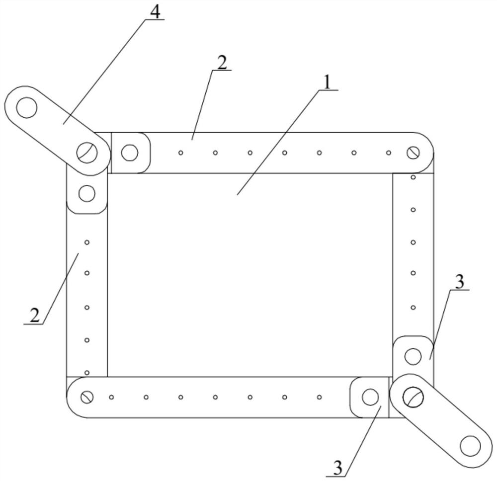
[0053] Such as Figure 1-Figure 5 As shown, the present embodiment provides a test device for testing shear performance, which includes a clamp, a connecting joint 3 and a loading joint 4, the clamp is detachably connected to the edge of the test piece 1, and the first edge of the test piece 1 is passed through the clamp. The load is applied diagonally; the two corners corresponding to the first diagonal are provided with a connecting joint 3 and a loading joint 4, one end of the connecting joint 3 is hinged to the fixture, and the other end is hinged to the loading joint 4, and the loading joint is connected to the testing machine. hinged.

[0054] The test device for testing the shear performance provided in this embodiment, the clamp is detachably connected to the edge of the test piece 1, and the load is applied along the first diagonal line of the test piece 1 through the clamp, and the two corners corresponding to the first diagonal line Both are provided with a connect...

Embodiment 2

[0067] The difference between the test device for testing the shear performance provided by the present embodiment and the first embodiment is:

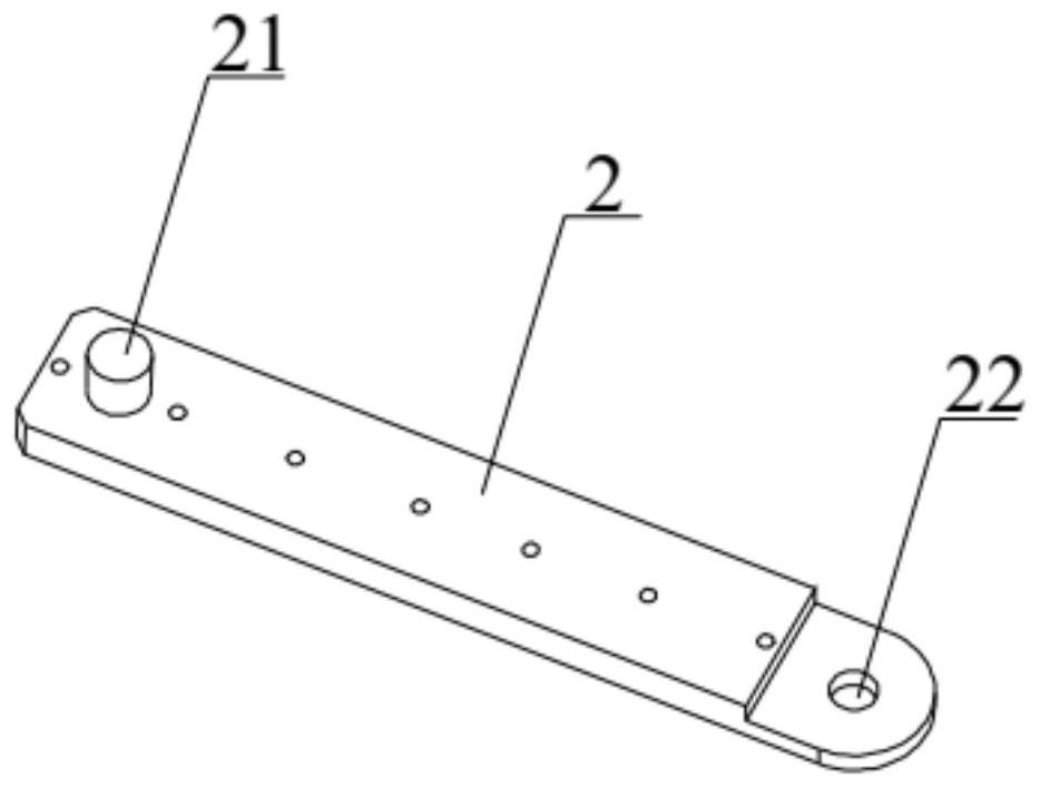
[0068] Such as Figure 12 As shown, a first connecting column 21 on each connecting plate 2 is arranged in the middle of the connecting plate 2. Adaptively, the length of the connecting joint 3 is relatively long, so that the first connecting hole 31 on the connecting joint 3 is connected to the first connecting hole 31. A connecting column 21 is matched and connected.

[0069] The bolt load of test piece 1 and the strain analysis of test piece 1 are carried out by the method of finite element analysis. Figure 13-Figure 17 It can be seen that an effect similar to that of Embodiment 1 is obtained.

Embodiment 3

[0071] The difference between the test device for testing the shear performance provided by the present embodiment and the first embodiment is:

[0072] Such as Figure 18 As shown, two first connecting columns 21 are arranged on each connecting plate 2, and each connecting plate 2 corresponds to two connecting joints 3, and the two connecting joints 3 are hinged. Specifically, among the two connecting joints 3 , one end of one connecting joint 3 is provided with a second connecting post 33 , and is hinged to the other connecting joint 3 through the second connecting post 33 . In this embodiment, the second connecting post 33 of one of the connecting joints 3 is hinged to the second connecting hole 32 of the other connecting joint 3 .

[0073] Using finite element analysis to analyze the loading condition of test piece 1, Figure 19 and Figure 20 The schematic diagrams of the analysis and simulation of the load parallel to the edge of the test piece 1 and the load perpendi...


PUM


Abstract

The invention discloses a test device for testing the shearing performance, and relates to the technical field of shearing performance testing. The test device for testing the shearing performance comprises a clamp, a connecting joint and a loading joint, the clamp is detachably connected with the edge of a test piece, a load is applied along a first diagonal line of the test piece through the clamp, the connecting joint and the loading joint are arranged on two corners corresponding to the first diagonal line, one end of the connecting joint is hinged with the clamp, the other end of the connecting rod is hinged with the loading joint, and the loading joint is hinged with a testing machine. According to the test device for testing the shearing performance, the connecting joint is hinged with the clamp and the loading joint, so that the load transmission is clear, the test load of near-pure shearing can be provided for the test piece, and the high-precision test loading is realized.

Description

technical field [0001] The invention relates to the technical field of shear performance testing, in particular to a test device for testing shear performance. Background technique [0002] Aircraft are generally thin-shell structures, and their stability is one of the important design factors. For siding structures such as civil aircraft, the allowable shear stress is one of the main bases for structural design, which is mainly determined and verified by test methods, and the test method is also the best way to determine the allowable shear stress. [0003] In the shear experiment, the shear load is transmitted to the inside of the test piece through the boundary of the test piece, and the design of the test fixture and the test piece has an important influence on the accuracy of the structural load transmission. At present, the shear load is mainly applied to the four sides of the square test piece by means of diagonal tension, in which the clamp connecting plate is conne...

Claims


Application Information

Patent Timeline
IPC IPC(8): G01N3/24
CPCG01N3/24G01N2203/0003G01N2203/0025G01N2203/0075G01N2203/0676G01N2203/0682
Inventor 石经纬冯荣欣胡忠民
Owner BEIJING AERONAUTIC SCI & TECH RES INST OF COMAC
Why Eureka
Try Eureka