Automatic slope speed control mechanism for common wheelchair

A wheelchair, a common technology, is used in vehicle rescue, patient chairs or special transport tools, medical transportation, etc. It can solve problems such as large physical exertion, loss of direction control, and difficulty in control, to improve safety and reliability. performance, increased frictional resistance, and good controllability

Active Publication Date: 2021-01-05
高敏丽
View PDF7 Cites 0 Cited by
  • Summary
  • Abstract
  • Description
  • Claims
  • Application Information

AI Technical Summary

Problems solved by technology

[0005] The invention provides a slope automatic speed control mechanism for ordinary wheelchairs, which can automatically lock in one direction when going uphill, and can automatically assist braking and deceleration when going downhill, without user's control, and is relatively safe. The advantages of high and good stability solve the problem that the existing ordinary wheelchairs mainly rely on the hands of the disabled to control the direction and forward direction through the rotary wheel. When the disabled go out alone and face uphill, not only It consumes a lot of physical strength, and if the hands leave the rotary wheel and use the handbrake to brake when going uphill, it is very easy to slip the car and lose control of the direction. The speed of the wheelchair will be gradually accelerated, because the user needs to control the direction of the wheelchair by manipulating the rotary wheel with both hands, so he can only use his hands to rub the rotary wheel to control the speed, but cannot use the handbrake to control the speed of the wheelchair, so it is very easy Causes scratches to the user's palm and is difficult to control its speed

Method used


Image

  • Automatic slope speed control mechanism for common wheelchair
  • Automatic slope speed control mechanism for common wheelchair
  • Automatic slope speed control mechanism for common wheelchair

Examples


Embodiment Construction

[0021] The following will clearly and completely describe the technical solutions in the embodiments of the present invention with reference to the accompanying drawings in the embodiments of the present invention. Obviously, the described embodiments are only some, not all, embodiments of the present invention. Based on the embodiments of the present invention, all other embodiments obtained by persons of ordinary skill in the art without making creative efforts belong to the protection scope of the present invention.

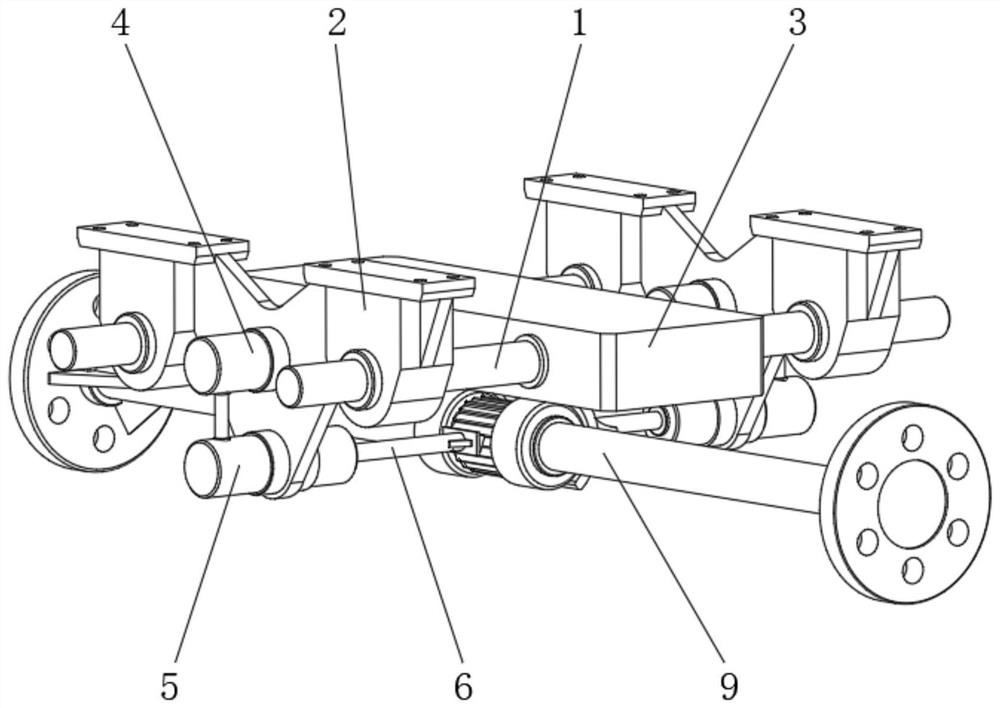
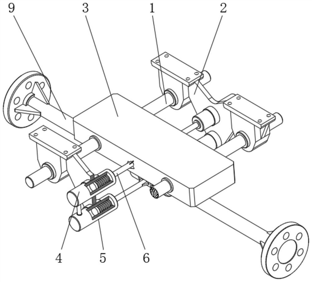
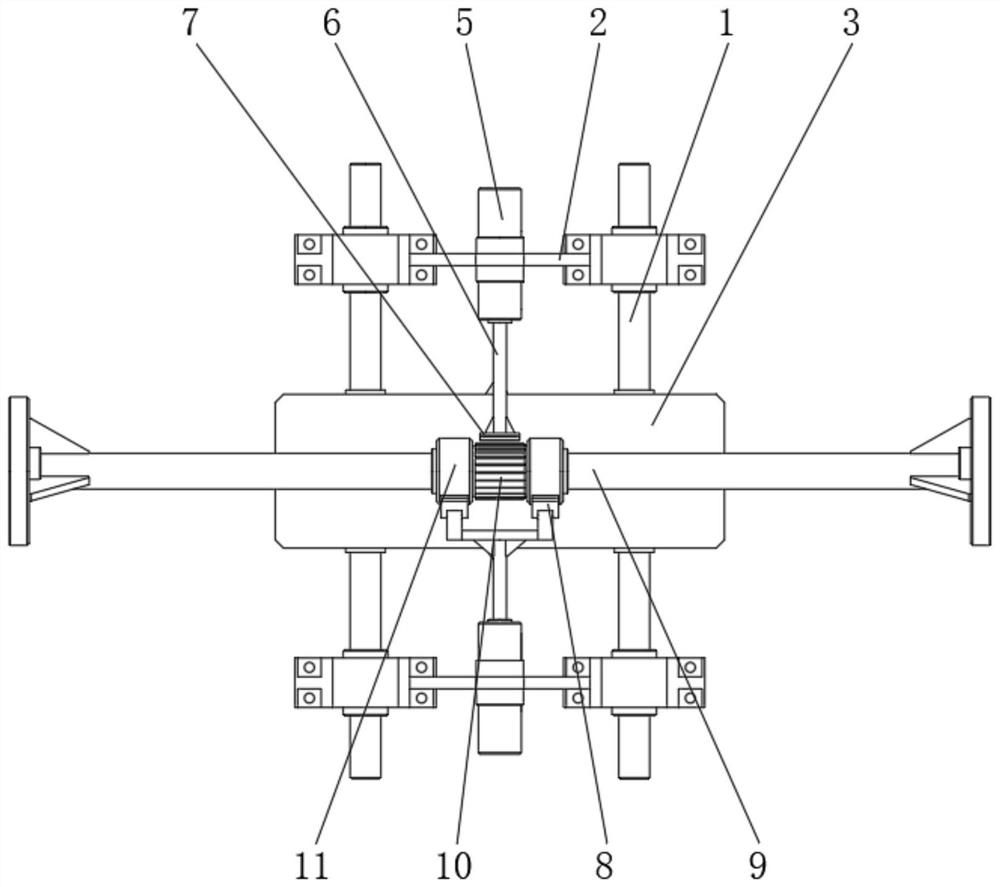
[0022] see Figure 1-5 , a slope automatic speed control mechanism for ordinary wheelchairs, including a fixed link 1 and a control spindle 9, the number of the fixed link 1 is set to two groups, and the two sides of the outer surface of the fixed link 1 are respectively fixedly installed with a set of Support 2, and the top of the installation support 2 is connected with the internal thread of the ordinary wheelchair, the wheel hub of the ordinary wheelchair ...


PUM


Abstract

The invention relates to the technical field of rehabilitation equipment, and discloses an automatic slope speed control mechanism for a common wheelchair. The automatic slope speed control mechanismcomprises two groups of fixed connecting rods and a control main shaft, two groups of mounting supports are fixedly mounted on two sides of the outer surfaces of the fixed connecting rods respectively, and the top ends of the mounting supports are in threaded connection with the interior of the common wheelchair. According to the automatic slope speed control mechanism for the common wheelchair, balancing weights movably connected to the fixed connecting rods in a sleeving mode are arranged so that a locking tooth block can be driven to lock a ratchet wheel to prevent slipping when the wheelchair goes uphill, friction plates can be driven to rub speed reduction disc bodies to provide certain friction braking force when the wheelchair goes downhill, the speed of the wheelchair in the downhill process is reduced, the whole linkage process is autonomously regulated and controlled through the influence of gravity borne by the balancing weights on the slope, manual operation is not needed,the flexibility is high, the controllability is good, and the safety and reliability of the wheelchair on the slope are effectively improved.

Description

technical field [0001] The invention relates to the technical field of health equipment, in particular to a slope automatic speed control mechanism for ordinary wheelchairs. Background technique [0002] As an important means of transportation for the disabled to carry out independent activities, wheelchairs can effectively meet the daily travel activities of the disabled, and carry out physical exercise or participate in social activities. Slopes or long downhill situations, and the existing ordinary wheelchairs mainly rely on the hand of the disabled person to carry out direction and forward control through the rotary wheel, when the disabled person goes out alone and faces the uphill, not only for other It consumes a lot of physical strength, and if you leave the rotary wheel and use the handbrake to brake when going uphill, it is very easy to slip the car and lose control of the direction. When facing downhill due to gravity, the speed of the wheelchair It will graduall...

Claims


Application Information

Patent Timeline
Patent Type & Authority Applications(China)
IPC IPC(8): A61G5/10
CPCA61G5/1032A61G5/1051A61G5/1086A61G2203/70
Inventor 付贤安
Owner 高敏丽
Why Eureka
Try Eureka