
Portable punch forming device

A stamping and forming, convenient technology, applied in forming tools, metal processing equipment, manufacturing tools, etc., can solve the problems of low efficiency, high labor cost, high price, etc., and achieve the effect of convenient use, low efficiency and simple structure

Pending Publication Date: 2021-01-05
湖南优德电子科技有限公司
View PDF7 Cites 0 Cited by
  • Summary
  • Abstract
  • Description
  • Claims
  • Application Information

AI Technical Summary

Problems solved by technology

[0002] Die stamping device refers to the forming device used in the mechanical manufacturing process. It is used for rapid, convenient, stamping and bending forming in any process in the process. For small bending and forming products, it is usually pressed and squeezed by hand. Punching and forming; while the existing stamping devices in the market are complex in structure and expensive; and usually one-to-one processing, which has low efficiency and high labor costs

Method used


Image

  • Portable punch forming device
  • Portable punch forming device

Examples


Embodiment Construction

[0014] In order to facilitate the understanding of the present invention, the present invention will be described in more detail below in conjunction with the accompanying drawings and specific embodiments. Preferred embodiments of the invention are shown in the accompanying drawings. However, the present invention can be implemented in many different forms and is not limited to the embodiments described in this specification. On the contrary, these embodiments are provided to make the understanding of the disclosure of the present invention more thorough and comprehensive.

[0015] It should be noted that "comb" in the present invention does not limit its specific structure to a "comb" type structure, and it can also be a "comb" type structure. The two are only different in the density of the comb teeth. The protected content of the invention does not constitute a limitation.

[0016] It should be noted that when an element is referred to as being “fixed” to another element...


PUM


Abstract

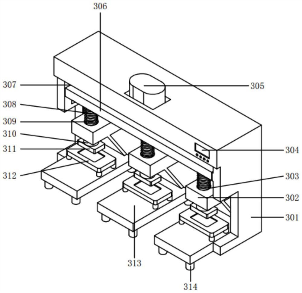
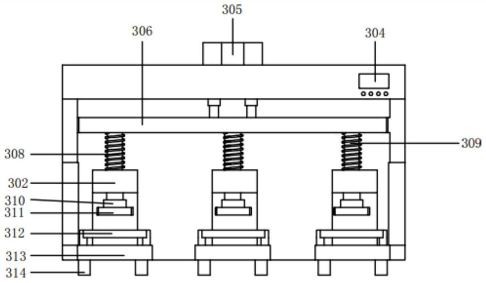
The invention discloses a portable punch forming device. The portable punch forming device comprises a device body, limiting plates, sliding sleeves, a control device, an air cylinder, a push plate, sliding blocks, springs, push rods, die sleeves, lower die frames, bottom plates and supporting columns. The supporting columns are arranged at the four corners of the bottom plates and on the lower plane of the device body; a lower die holder is arranged on the front side of the upper end of each bottom plate; the air cylinder is arranged at the upper end of the device body and connected with thewire control device; an air rod at the lower end of the cylinder is fastened to the push plate; the sliding blocks are arranged at the left side and the right side of the push plate and matched with plane sliding grooves in the device body; the limiting plates are welded to the lower end of the plane in the device body; the sliding sleeves are arranged in countersunk through holes in the middles of the limiting plates; the springs are arranged on the outer planes of the push rods; and the lower ends of the push rods are matched with the die sleeves. According to the portable punch forming device, automatic punch forming is facilitated, and the push rods can be rapidly assisted to return upwards through the springs; and the device is simple in structure and convenient to use.

Description

technical field [0001] The invention relates to the technical field of fixtures, in particular to a portable punching and forming device. Background technique [0002] Die stamping device refers to the forming device used in the mechanical manufacturing process. It is used for rapid, convenient, stamping and bending forming in any process in the process. For small bending and forming products, it is usually pressed and squeezed by hand. Punching and forming; while the existing stamping devices in the market are complex in structure and expensive; and usually one-to-one processing, so the efficiency is low and the labor cost is high. Contents of the invention [0003] The technical problem to be solved by the present invention is to provide a convenient stamping and forming device, which solves the problem of manual pressing and forming; multiple products can be processed at the same time, so that the efficiency is high and the labor cost is low. [0004] In order to solve...

Claims


Application Information

Patent Timeline
Patent Type & Authority Applications(China)
IPC IPC(8): B21D22/02B21D37/10
CPCB21D22/02B21D37/10
Inventor 严冬冬
Owner 湖南优德电子科技有限公司
Learn More