

Large-aperture reflection optical system detection device and method
A technology of reflection optics and detection device, which is used in measurement devices, optical instrument testing, and optical performance testing, etc., can solve the problems of high economic cost, long test adjustment time, and inability to measure the image quality of multiple fields of view of an optical system at the same time. Achieving a wide range of effects
- Summary
- Abstract
- Description
- Claims
- Application Information
AI Technical Summary
Problems solved by technology
Method used
Image

Examples
Embodiment Construction
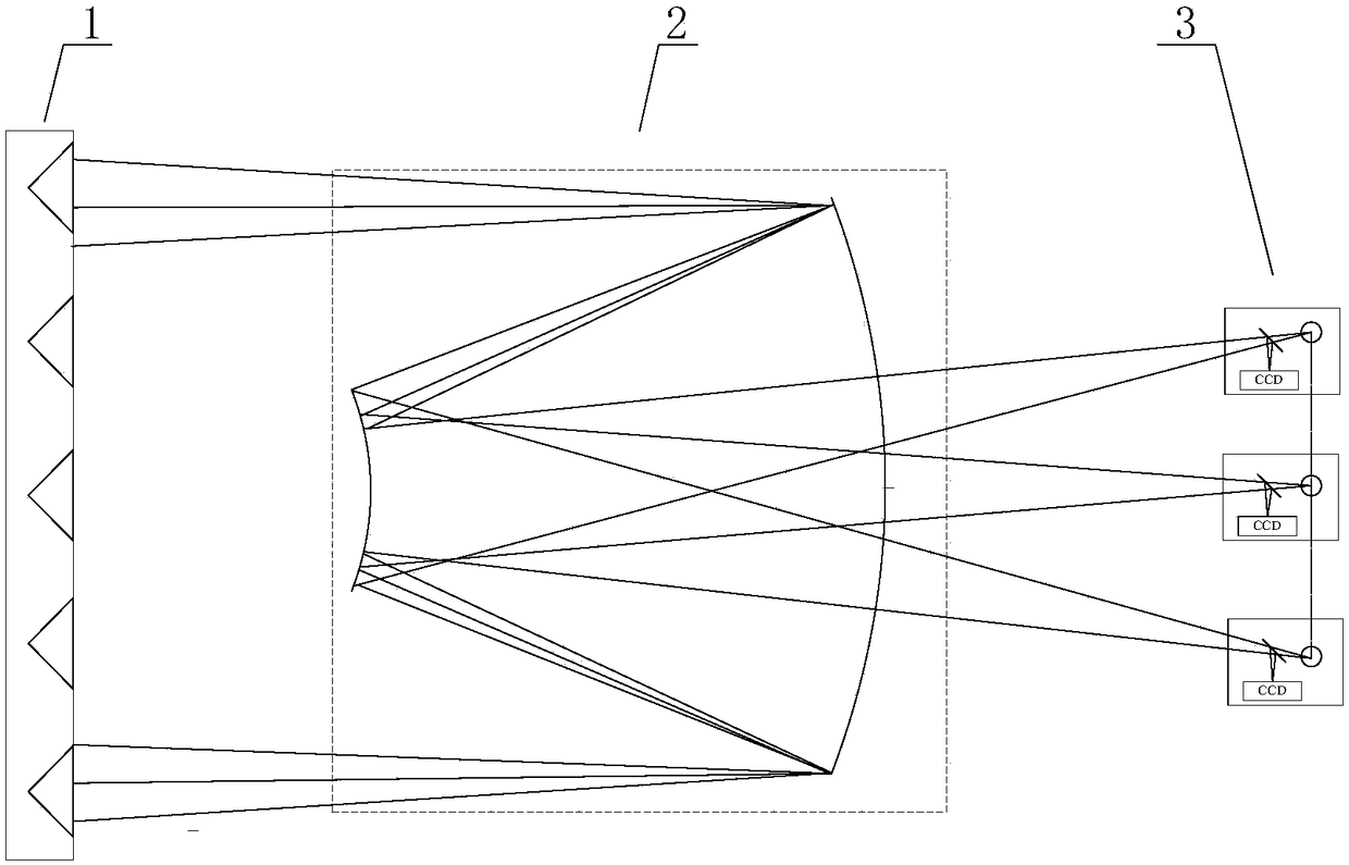
[0036] Such as figure 1 As shown, the large-aperture reflective optical system detection device based on the corner cube array of the present invention is composed of a corner cube array 1 , a large-aperture reflective optical system to be tested 2 , and a point light source emitting and receiving device 3 .
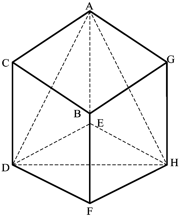
[0037] The corner cube array 1 comprises a plurality of corner cubes arranged in a matrix (the corner cube is formed by cutting a corner in a cube), and the corner cube includes three conical surfaces and a bottom surface, wherein three The two cones are perpendicular to each other, and the base is an isosceles triangle;
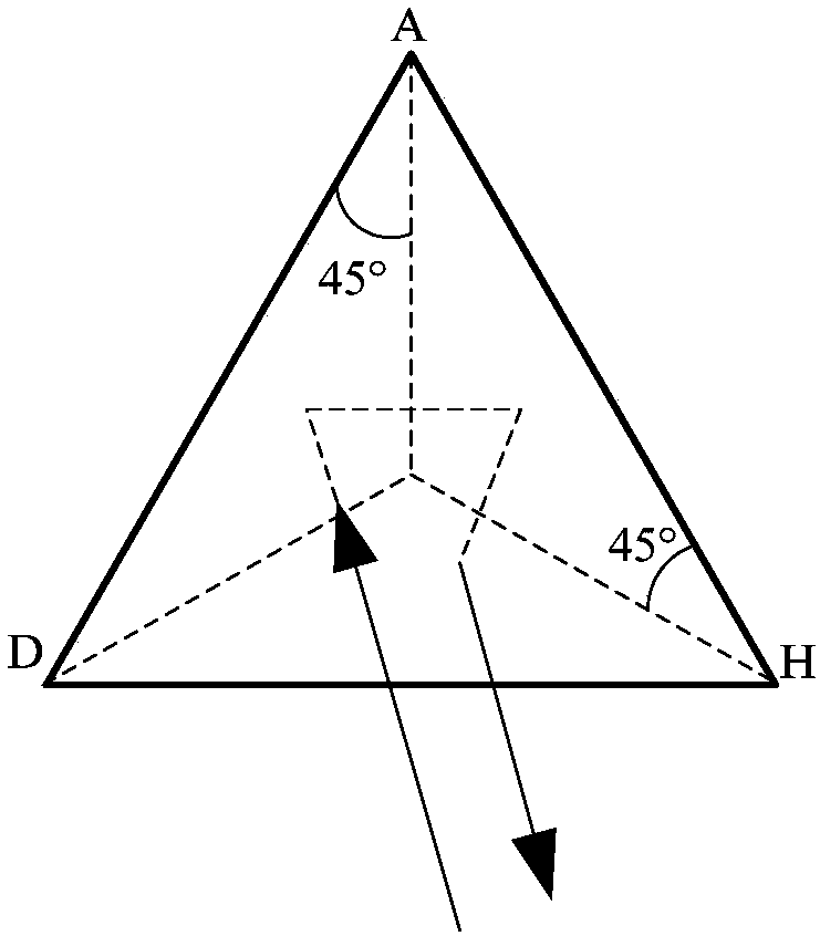
[0038] The bottom surfaces of all corner cubes in the corner cube array 1 are all facing the large-aperture reflective optical system 2 to be measured (for any corner cube: the incident light beam entering the corner cube at any angle is incident from its bottom surface, passes through three After the first conical surface is reflected successively, i...
PUM
 Abstract
Description
Claims
Application Information