
Automatic take-up type ink box

A linear and automatic technology, applied in the direction of conveying filamentous materials, workshop equipment, manufacturing tools, etc., can solve the problem that the ink fountain cannot be automatically retracted, and achieve the effect of simple, fast and convenient operation.

Active Publication Date: 2021-01-05
国网山东省电力公司建设公司 +2
View PDF6 Cites 0 Cited by
  • Summary
  • Abstract
  • Description
  • Claims
  • Application Information

AI Technical Summary

Problems solved by technology

[0005] Aiming at the deficiencies of the prior art, the present invention provides an automatic thread-retracting ink cartridge, which solves the problem that the ink fountain cannot automatically retract the thread and remove the dust on the ink thread

Method used


Image

  • Automatic take-up type ink box
  • Automatic take-up type ink box
  • Automatic take-up type ink box

Examples


Embodiment 1

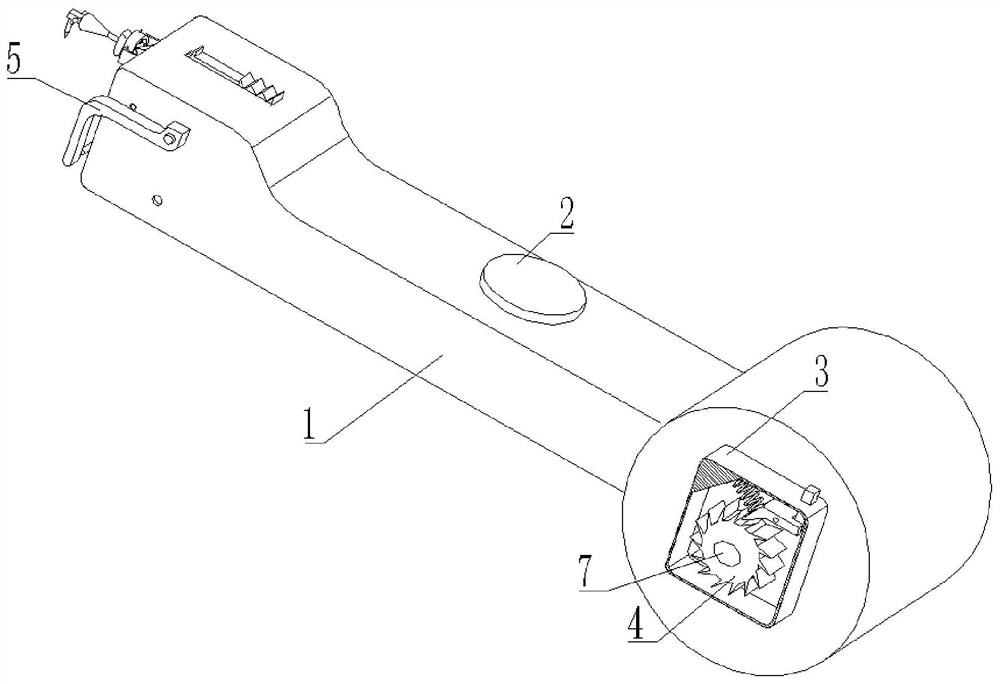
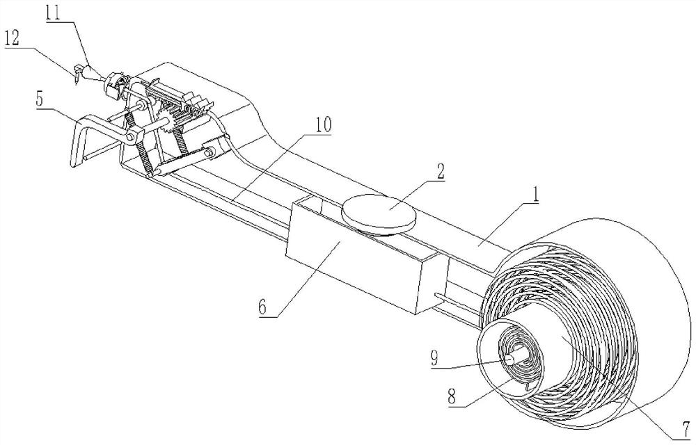
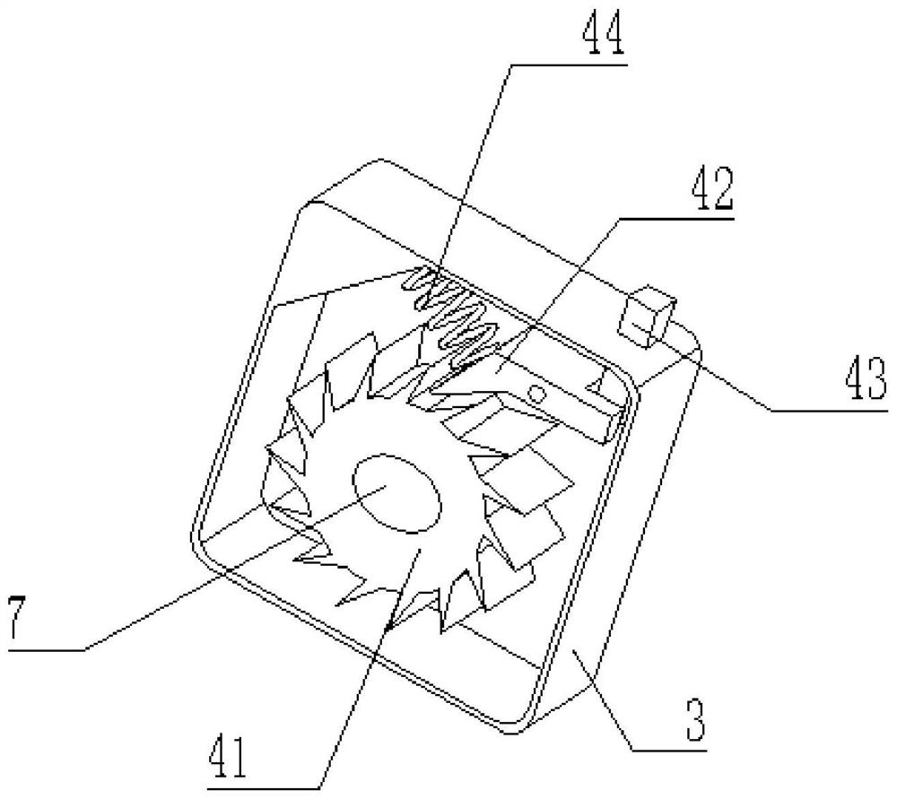
[0033] see Figure 1-5 , an automatic take-up type ink cartridge, comprising a box body 1, the upper surface of the box body 1 is threadedly connected with a threaded cover 2, the inside of the box body 1 is connected with an ink tank 6 by bolts, and the inner wall of the box body 1 is connected with a rotary The sleeve 7, the inner wall of the box body 1 is fixedly connected with the reel 9, the reel 9 is located inside the rotary sleeve 7, a coil spring 8 is arranged between the rotary sleeve 7 and the reel 9, and one end of the coil spring 8 is fixedly connected with the inner wall of the rotary sleeve 7 , the other end of coil spring 8 is fixedly connected with the surface of reel 9, and the left side of box body 1 is provided with control mechanism 5, and the front portion of box body 1 is welded with side box 3, and the inside of side box 3 is provided with fixing mechanism 4.

[0034] Further, the surface of the rotary sleeve 7 is wound with an ink thread 10, one end of...

Embodiment 2

[0040] see Figure 6-Figure 7 , the cleaning device 505 includes a cleaning sleeve 5051, the surface of the cleaning sleeve 5051 is fixedly connected with a support plate 5054, the surface of the support plate 5054 is fixedly connected with a sliding pole 5055, and the surface of the sliding pole 5055 is slidingly connected with a circular sleeve 5052, and the circular sleeve The surface of 5052 is fixedly connected with connecting plate 5053, and the right side of connecting plate 5053 is fixedly connected with the left side of box body 1.

[0041] Further, there are three cleaning sleeves 5051, and the three cleaning sleeves 5051 are distributed in a circular array with the center of the circle sleeve 5052 as the axis of symmetry. The effect is to press the three cleaning sleeves 5051 tightly on the ink line 10, so that the diameter of the three cleaning sleeves 5051 can be enlarged or reduced, and the cleaning of the ink line 10 can be better cleaned. The effect is the bes...


PUM


Abstract

The invention relates to the technical field of ink fountains and discloses an automatic take-up type ink box which comprises a box body, the upper surface of the box body is in threaded connection with a threaded cover, the interior of the box body is connected with an ink adding box through a bolt, the inner wall of the box body is rotationally connected with a rotating sleeve, and the inner wall of the box body is fixedly connected with a reel. The reel is located in the rotating sleeve, a coil spring is arranged between the rotating sleeve and the reel, one end of the coil spring is fixedly connected with the inner wall of the rotating sleeve, a control mechanism is arranged on the left side of the box body, and a fixing mechanism is arranged in a side box. According to the automatic take-up type ink box, an ink line can drive the rotating sleeve to rotate in the pulling process, the rotating sleeve can drive the coil spring to contract in the rotating process, the gaps between theinteriors of the coil spring can become small, contraction is achieved, the coil spring can provide restoring force, the automatic take-up function on the ink line is achieved, and the problems thatmanual take-up operation is low in efficiency, time and labor are wasted are directly solved.

Description

technical field [0001] The invention relates to the technical field of ink fountains, in particular to an automatic take-up type ink box. Background technique [0002] The ink cartridge, also known as the ink fountain, is composed of four parts: the ink tank, the wire wheel, the ink line, and the ink stick. It is a very common tool in the traditional Chinese woodworking industry. Now the ink fountain is usually used in house construction. [0003] At present, many even ink cartridges are still manually wound up during use, which is not only time-consuming, but also easily affects the efficiency of work. At the same time, the ink line needs to be spring pressed during the use of the ink fountain, and some dust is easy to adhere to the ink line. Into the middle of the ink fountain, causing a certain degree of damage to the use of the entire ink fountain, so an automatic take-up type ink cartridge is proposed to solve the above-mentioned problems. Contents of the invention ...

Claims


Application Information

Patent Timeline
IPC IPC(8): B25H7/04B65H75/48B65H75/44B65H71/00
CPCB25H7/04B25H7/045B65H75/486B65H75/4428B65H75/4457B65H71/00B65H2701/30
Inventor 曹东明郭峰陈永辉钱鹏李斌张松孙丰佳李东阳王璐安仲杰肖鹏陈红利孙瑞
Owner 国网山东省电力公司建设公司
Learn More