Engineering vehicle cooling system with exhaust injection cooling device

A technology for cooling systems and engineering vehicles, which is applied in the control of coolant flow, engine cooling, engine components, etc., and can solve problems such as inability to meet heat dissipation requirements, large cooling system resistance, and large combined wind resistance of radiator modules

Inactive Publication Date: 2021-01-05
JIANGSU XCMG CONSTR MASCH RES INST LTD
View PDF11 Cites 1 Cited by
  • Summary
  • Abstract
  • Description
  • Claims
  • Application Information

AI Technical Summary

Problems solved by technology

[0004] Both methods of vehicle cooling system layout in the prior art have defects. The first method has two defects: on the one hand, for radiator single-row parallel arrangement, it often requires a large layout space and can only be used Because there are fewer cooling modules in the whole vehicle (some models may only have one or a combination of water radiator, hydraulic oil radiator, transmission oil radiator, air-to-air cooler, air-conditioning condenser and fuel cooler), and The space in the power cabin is sufficient; on the other hand, for the arrangement of multiple rows of radiators in series, some models contain more cooling modules, and the space in the power cabin is limited, so multiple rows in series can only be used. In this way, the resistance of the cooling system is too large, and only Increase the static pressure of the fan, and must meet the air volume requirements, which leads t

Method used


Image

  • Engineering vehicle cooling system with exhaust injection cooling device
  • Engineering vehicle cooling system with exhaust injection cooling device

Examples


Embodiment Construction

[0026]The present invention will be further described below in conjunction with the drawings. The following embodiments are only used to illustrate the technical solutions of the present invention more clearly, and cannot be used to limit the protection scope of the present invention.

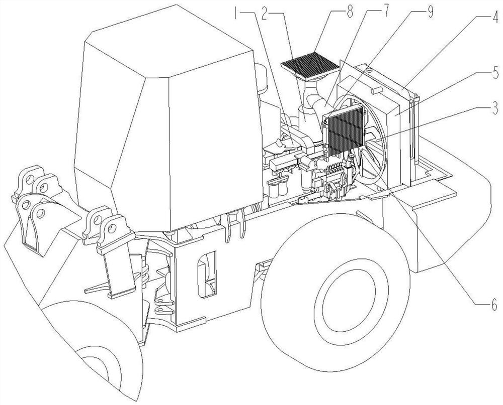
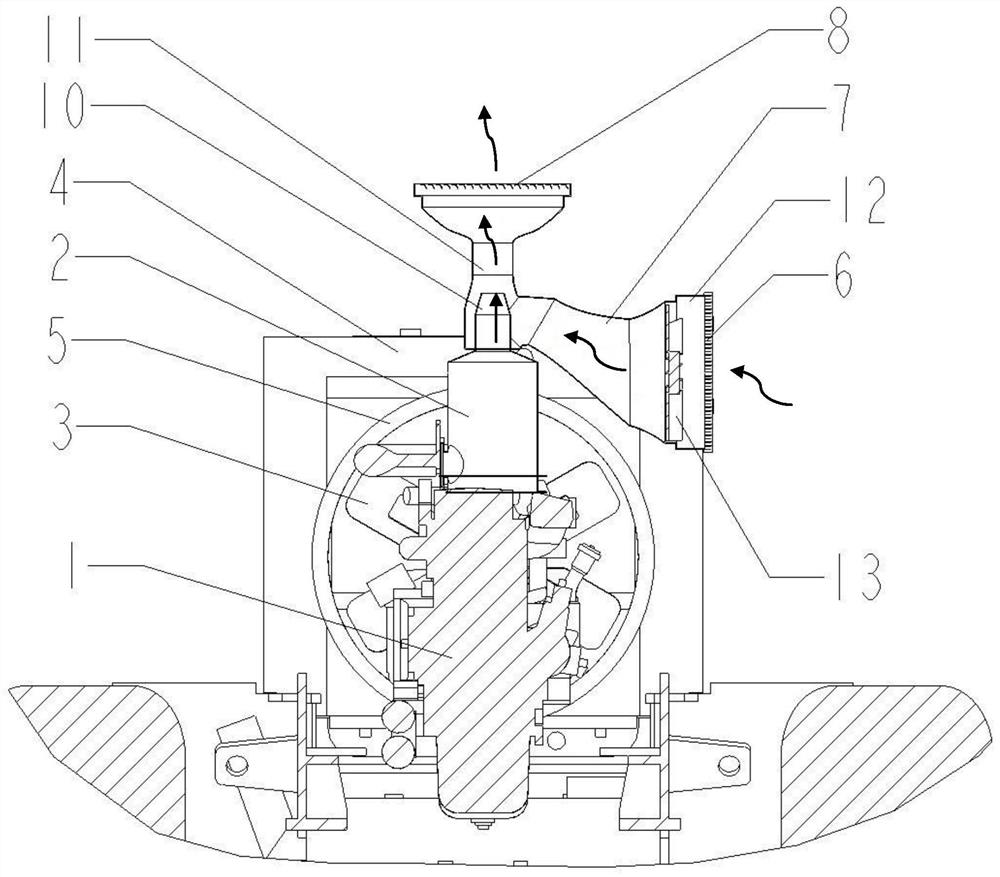
[0027]The invention provides an engineering vehicle cooling system with an exhaust ejection cooling device, which combines a traditional fan radiator cooling system and an exhaust ejection cooling system, and correspondingly, a main cooling system and a sub cooling system are independently provided. The main cooling system includes a fan driven by an engine or a hydraulic motor and a combination of at least one or several modules of a water radiator, a hydraulic oil radiator, a transmission oil radiator, and an air-to-air cooler with large heat dissipation power. The sub-cooling system includes at least one or a combination of several modules, such as an exhaust ejection system, an electronic fan, and a...


PUM


Abstract

The invention discloses an engineering vehicle cooling system with an exhaust injection cooling device, comprising a main cooling system and an auxiliary cooling system, wherein the main cooling system comprises a fan driven by an engine or a hydraulic motor and at least one or a combination of several modules of a water radiator, a hydraulic oil radiator, a transmission oil radiator and an air-air intercooler which are high in heat dissipation power; and the auxiliary cooling system comprises an exhaust injection system, an electronic fan and at least one or a combination of several modules of an air conditioner condenser, a fuel oil cooler and the like which are small in heat dissipation power. Air drive force needed by heat dissipation of the auxiliary cooling system is mainly providedby the exhaust injection system, so that the electronic fan can operate only when the drive force is insufficient, the drive force is compensated, and drive force is guaranteed to be continuous and sufficient. The engineering vehicle cooling system can meet heat dissipation requirement of a cooling system, also can save power consumption of the fan, and reduces noises.

Description

Technical field[0001]The invention belongs to the technical field of engineering machinery, and in particular relates to an engineering vehicle cooling system with an exhaust ejection cooling device.Background technique[0002]As an important equipment for engineering construction, construction machinery has large power, large torque, complex and harsh working conditions, many heating components during work, and large heat dissipation requirements. Its heat source includes not only engine water jackets, but also hydraulic actuators, Transmission systems, turbocharging systems, air conditioning systems, fuel cooling systems, etc. require more heat to be taken away by the cooling medium. Construction machinery travels slowly, and there is almost no oncoming wind. It is necessary to use a fan to force suction or blow to cool the system.[0003]In the prior art, there are mainly two ways to arrange the cooling system of the whole vehicle. One is the traditional fan radiator structure, in wh...

Claims


Application Information

Patent Timeline
IPC IPC(8): F01P5/08F01P5/02F01P5/04F01P5/06F01P7/02F01P7/04F01P7/08
CPCF01P5/02F01P5/04F01P5/06F01P5/08F01P7/026F01P7/048F01P7/08F01P2005/025F01P2005/046
Inventor 高磊磊汪三龙苏俊收
Owner JIANGSU XCMG CONSTR MASCH RES INST LTD
Why Eureka
Try Eureka