A reactor double-plate equal flow flow distribution device and flow distribution structure

A flow distribution device and flow distribution technology, applied in the field of nuclear power, can solve problems such as uneven flow distribution, achieve the effects of easy replacement and maintenance, compact and simple structure, and ease eddy currents

Active Publication Date: 2022-02-01
NUCLEAR POWER INSTITUTE OF CHINA
View PDF10 Cites 0 Cited by
  • Summary
  • Abstract
  • Description
  • Claims
  • Application Information

AI Technical Summary

Problems solved by technology

[0004] The purpose of the present invention is to provide a reactor double-plate equal-flow flow distribution device, which solves the problem of uneven flow distribution caused by the existing flow distribution structure, and has the advantages of compact and simple structure, which is convenient for replacement and maintenance

Method used


Image

  • A reactor double-plate equal flow flow distribution device and flow distribution structure
  • A reactor double-plate equal flow flow distribution device and flow distribution structure
  • A reactor double-plate equal flow flow distribution device and flow distribution structure

Examples


Embodiment 1

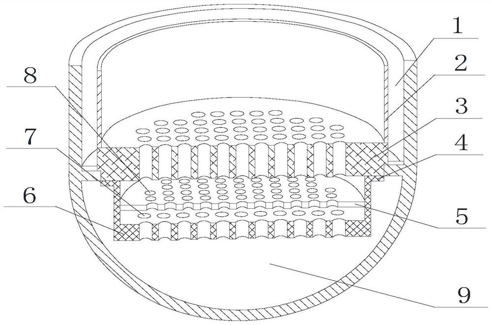
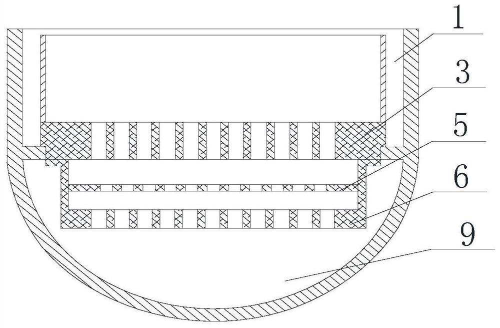
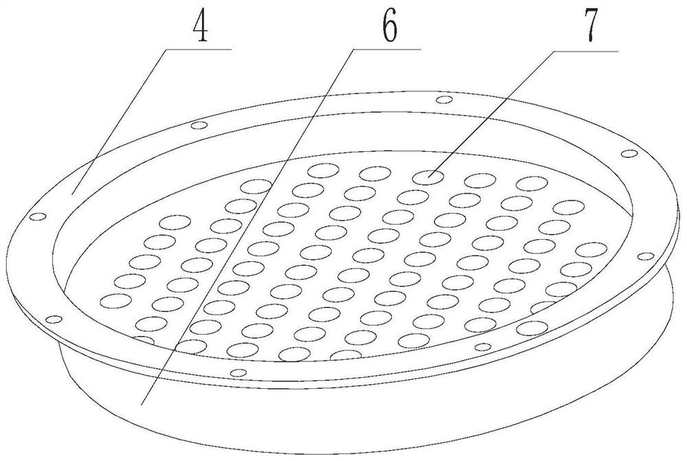
[0046] like Figure 1-Figure 4 As shown, a reactor double-plate equal-flow flow distribution device includes a pressure vessel, a hanging basket 2 and a support plate 3 under the core, the hanging basket 2 is arranged in the pressure vessel, and the outer wall of the hanging basket 2 is connected to the pressure vessel An annular descending chamber 1 is formed between the inner walls. The core lower support plate 3 is arranged at the bottom of the hanging basket 2. The bottom of the pressure vessel forms a lower chamber 9 below the core lower support plate 3. The core The lower support plate 3 is provided with a number of through holes, and also includes a secondary flow equalizer 5 and a flow distribution cylinder 6, the flow distribution cylinder 6 is installed in the lower chamber 9, one end of the flow distribution cylinder 6 is an open end, and the other end It is a closed end, and the beginning of the flow distribution cylinder 6 is connected to the bottom of the lower s...

Embodiment 2

[0050] like Figure 1-Figure 4 As shown, this embodiment is based on Embodiment 1, and the aperture of the second flow hole 8 is 1 / 3 to 1 / 2 of the aperture of the first flow hole 7; the number of first flow holes on the flow distribution cylinder 6 7 have the same aperture; the apertures of several second flow holes 8 on the secondary equalizer plate 5 are the same; several first flow holes 7 are evenly distributed on the flow distribution cylinder 6, and some second flow holes 8 Evenly distributed on the flow plate 5.

Embodiment 3

[0052] like Figure 1-Figure 4 As shown, this embodiment is based on Embodiment 1, the distance between the bottom of the flow distribution cylinder 6 and the bottom of the lower chamber 9 is consistent with the height of the flow distribution cylinder 6; the secondary flow equalizer 5 and the core lower support plate 3 The distance between them is 1 / 2 of the height of the flow distribution cylinder 6 .


PUM


Abstract

The invention discloses a reactor double-plate equal-flow flow distribution device and a flow distribution structure. The distribution device includes a pressure vessel, a hanging basket and a support plate under the core. A descending cavity is formed between the outer wall of the hanging basket and the inner wall of the pressure vessel. The core The lower support plate is arranged at the bottom of the hanging basket, and the bottom of the pressure vessel forms a lower chamber. The lower support plate of the core is provided with through holes, and also includes a secondary flow equalizer and a flow distribution cylinder. The flow distribution cylinder is installed in the lower chamber. One end of the flow distribution cylinder is an open end, and the other end is a closed end. The open end of the flow distribution cylinder is connected to the bottom of the lower support plate of the core. The closed end of the flow distribution cylinder is provided with a number of first flow holes, and the secondary flow equalizer is installed In the flow distribution cylinder, several second flow holes are arranged on the secondary flow equalizer plate, and the first flow holes and the second flow holes are arranged alternately. The invention solves the problem of uneven flow distribution caused by the existing flow distribution structure, has the advantages of compact and simple structure, and is convenient for replacement and maintenance.

Description

technical field [0001] The invention relates to the technical field of nuclear power, in particular to a reactor double-plate equal-flow flow distribution device and a flow distribution structure. Background technique [0002] The pressurized water reactor of a nuclear power plant is composed of reactor pressure vessels, reactor internals, core components and other components. The reactor internals, the inner wall of the pressure vessel and the structure of the fuel assembly constitute the passage for the coolant to flow. The coolant flows in from the inlet of the reactor pressure vessel through the cold pipe section and the hot pipe section respectively, and changes the flow direction by hitting the outer wall of the hanging basket. Under the action of gravity, most of the coolant flows downward and mixes with other coolants. The existence of the pipe section leads to the asymmetry of the flow of the coolant, and the flow situation is more complicated, which finally leads ...

Claims


Application Information

Patent Timeline
Patent Type & Authority Patents(China)
IPC IPC(8): G21C19/04G21C15/12
CPCG21C19/04G21C15/12Y02E30/30
Inventor 罗英张显均李娜于天达王仲辉李燕刘卢果李浩何培峰胡雪飞王东辉颜达鹏王庆田舒翔胡朝威张翼郭超陈忻
Owner NUCLEAR POWER INSTITUTE OF CHINA
Why Eureka
Try Eureka