Space locator used in cooperation with electromagnetic navigation system and C arm

An electromagnetic navigation and spatial positioning technology, applied in surgical navigation systems, stereotaxic surgical instruments, medical science, etc., can solve problems such as difficulty in predicting patient injury, inability to effectively complete registration, increasing risks, and reducing operation time. and blood loss, reduce surgical complications, and reduce the effect of secondary injury

Active Publication Date: 2021-01-08
山东威高医疗科技有限公司
View PDF15 Cites 5 Cited by
  • Summary
  • Abstract
  • Description
  • Claims
  • Application Information

AI Technical Summary

Problems solved by technology

[0002]Magnetic navigation system is often used in orthopedic field for minimally invasive surgery, and the registration method of selecting feature points is mostly suitable for open surgery. In the minimally invasive surgery process, it is impossible to provide too many feature points for selection, and the registration cannot be completed effectively. Moreover, for open surgery, most of the feature point selection process relies on the medical staff. Work experience is used to select the position, and at the same time, it is inevitable to touch the patient's bones and surrounding tissues when using the registration tool for registration. In summary, the registration method of selecting feature points not only has great limitations, but also exists A certain probability increases the risk during the operation, and it is difficult to predict the harm to the patient during the operation before the operation

Method used


Image

  • Space locator used in cooperation with electromagnetic navigation system and C arm
  • Space locator used in cooperation with electromagnetic navigation system and C arm
  • Space locator used in cooperation with electromagnetic navigation system and C arm

Examples


Embodiment Construction

[0015] The specific implementation manners of the present application will be further described below in conjunction with the accompanying drawings.

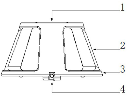
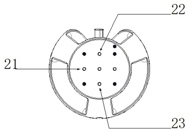
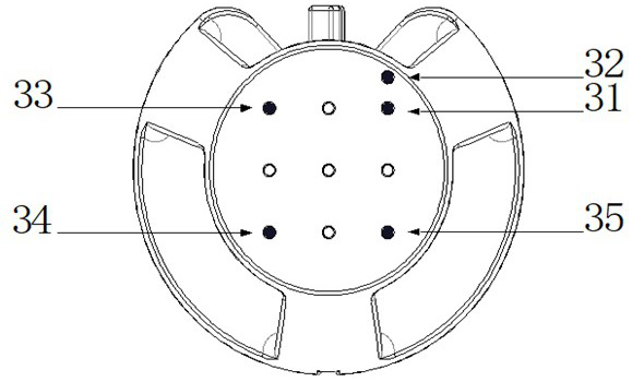
[0016] Such as Figure 1-6 As shown, the space locator used in conjunction with the electromagnetic navigation system and the C-arm involved in the present application includes a main body, a tracking unit installed on the main body, and a compression coil knob 4 for fixing the tracking unit. In this embodiment, the main body may include an upper end portion 1 , a lower end portion 3 and a connecting portion 2 connecting the upper end portion 1 and the lower end portion 3 . The size of the upper surface of the main body is different from that of the lower surface, and at least six grooves are provided on the upper surface of the main body, at least three of which are used as calibration points for calibrating the space locator, at least Steel balls whose size matches the grooves are placed in the three grooves, and the steel ba...


PUM


Abstract

The invention provides a space locator used in cooperation with an electromagnetic navigation system and a C arm. The space locator comprises a body, a tracking unit installed on the body and a pressing coil rotary knob used for fixing the tracking unit, wherein the upper surface and the lower surface of the body are different in size; the upper surface and the lower surface of the body are each provided with at least six grooves; at least three grooves serve as calibration points; steel balls matched with the grooves in size are placed in the at least three grooves and used for registration in an operation; the grooves serving as the calibration points are the same in size, and the steel balls in the upper surface and the lower surface of the body are different in size; an installation groove for containing the tracking unit is formed in the large-size surface of the upper surface and the lower surface of the body; the tracking unit comprises an electromagnetic induction coil connected with a wire; and the tail end of the wire is connected with a plug used for being connected with the electromagnetic navigation system. After the space locator is connected with the electromagneticnavigation system, the space locator can be used for effective registration in both an open operation and a minimally invasive operation.

Description

technical field [0001] The invention relates to the technical field of electromagnetic navigation system registration, in particular to a spatial locator used in cooperation with an electromagnetic navigation system and a C-arm. Background technique [0002] The magnetic navigation system is often exposed to minimally invasive surgery in the field of orthopedics, and the registration method of selecting feature points is mostly suitable for open surgery, and cannot provide too many feature points in the process of minimally invasive surgery If the selection is performed, the registration cannot be effectively completed, and for open surgery, most of the feature point selection process relies on the work experience of the medical staff to select the position, and at the same time when using the registration tool for registration It is inevitable to touch the patient's bones and surrounding tissues. In summary, the registration method of selecting feature points not only has g...

Claims


Application Information

Patent Timeline
Patent Type & Authority Applications(China)
IPC IPC(8): A61B34/20A61B90/11
CPCA61B34/20A61B90/11A61B2034/2051A61B2034/2065
Inventor 王炳强谷鹏孙之建
Owner 山东威高医疗科技有限公司
Why Eureka
Try Eureka