Oil discharge device and steamer

A technology of oil discharge device and steamer, which is applied in the field of steamer, can solve the problems of affecting the quality of fabrics, unable to disperse oil fume in time, and achieve the effect of improving production quality

Active Publication Date: 2022-05-31
无锡市信谊机械有限公司
View PDF18 Cites 0 Cited by
  • Summary
  • Abstract
  • Description
  • Claims
  • Application Information

AI Technical Summary

Problems solved by technology

[0005] The purpose of the present invention is to disclose an oil discharge device and a steaming machine, which is used to solve the problem that the steaming machine in the prior art cannot discharge the oil fumes in time and affect the quality of the fabric.

Method used


Image

  • Oil discharge device and steamer
  • Oil discharge device and steamer
  • Oil discharge device and steamer

Examples


Embodiment Construction

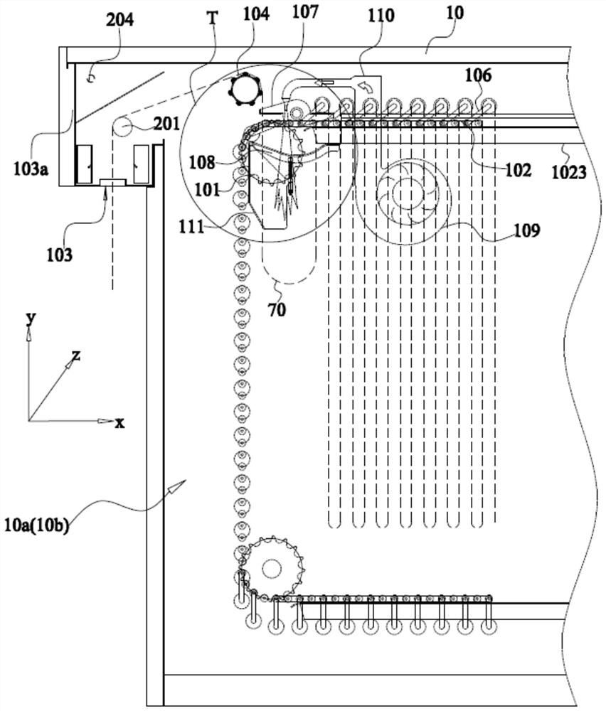
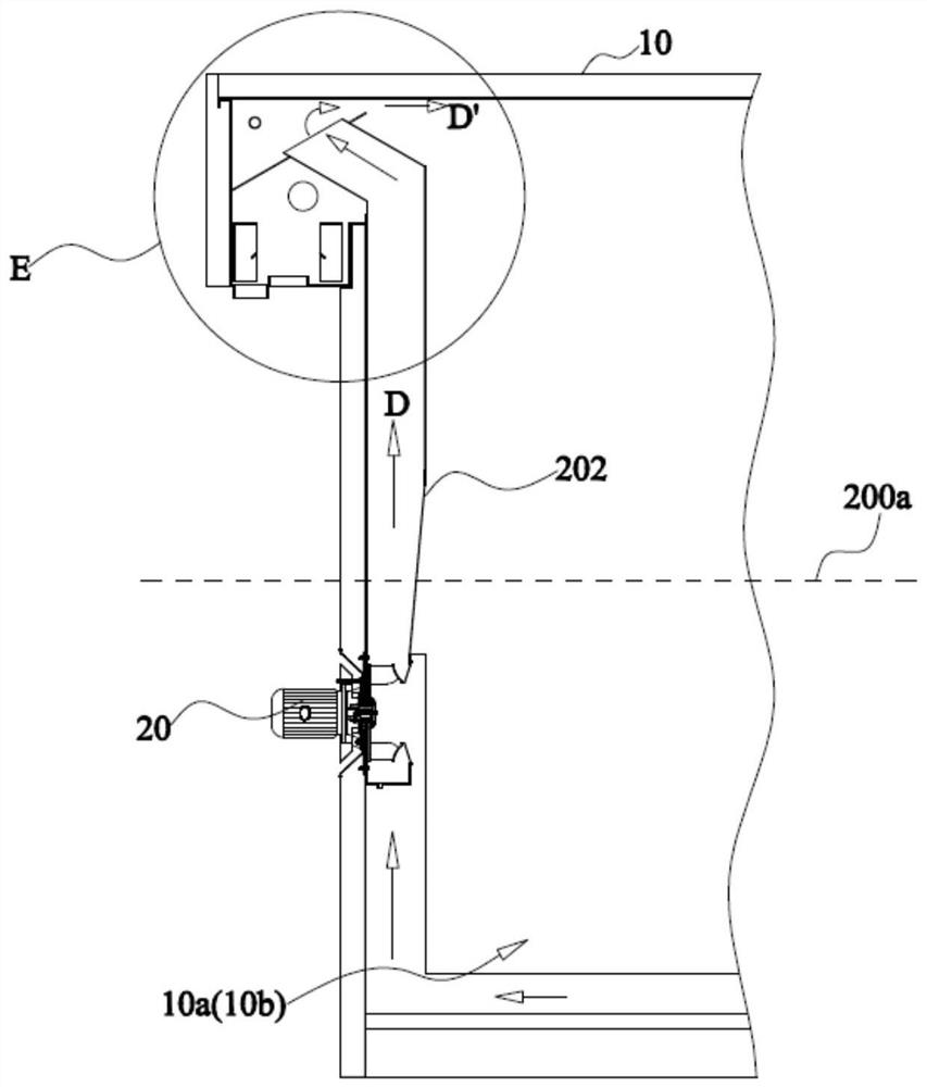
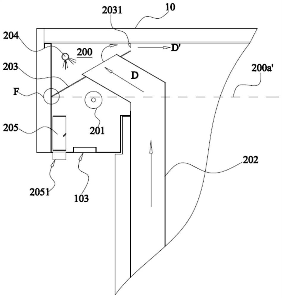
[0047] Please refer to a specific implementation of a steaming machine according to an embodiment of the present invention shown in FIG. 1 to FIG. 10 .

[0053] Wherein, the top of the anti-drip plate 203 is lower than the free end of the anti-drip plate 203, and the top of the anti-drip plate 203 is formed to drain oil

[0057] In this embodiment, the steamer makes the cloth rest roller 105 move through the crank assembly 106 connected to both sides of the cloth rest roller 105.

[0060] Continue to describe with reference to FIG. 1 and FIG. 6, in any of the above-mentioned embodiments, a support seat is arranged below the support plate 108

[0061] It should be noted that the horizontal section of the support plate 108 is configured as an arc shape, and the recessed portion of the support plate 108 is gradually oriented

[0064] The series of detailed descriptions listed above are only specific to the possible embodiments of the present invention.

[0065] Furthermore, it should ...


PUM


Abstract

The invention provides an oil discharge device and a steamer. A feed port and a discharge port are formed above both sides of the steamer box, a feed roller is arranged above the feed port, and a feed roller is arranged above the discharge port. The discharge roller and the second circulating fan are arranged on both sides of the steamer casing, wherein the oil discharge device includes: arranged obliquely above the feed roller and / or the discharge roller and reserved with the top of the steamer casing An anti-drip plate with a preset gap, an oil discharge hole is formed at the lower end of the anti-drip plate; and an oil discharge pipe arranged under the oil discharge hole to receive the oil fume and discharge the oil fume outside the steamer box; wherein, the first The air outlet end of the secondary circulation fan runs through the anti-drip plate, forming a hot air circulation space above the side of the anti-drip plate, so that the gas flowing from the air outlet end to the hot air circulation space can flow into the steamer box from the preset gap. The invention solves the problem that the quality of the fabric is affected because the steamer in the prior art cannot disperse oily smoke in time during operation.

Description

An oil discharge device and a steamer technical field [0001] The present invention relates to the technical field of steaming machines, and more particularly to an oil discharge device and a steaming machine. Background technique Along with the development of science and technology, the improvement of people's living standards, the requirement to the printing quality of fabric is also gradually improved. The steaming machine has also been developed from the guide roller type to the long ring type to meet the requirements of low fabric tension. And, make the connection between the fabric and the roller body The contact surface is changed from double-sided to single-sided, that is, the printing surface of the fabric is never in contact with the roller body to avoid the phenomenon of overlapping colors. Generally speaking, the steaming machine will produce oil fume in the steaming chassis during high temperature dispersion operation, if the oil fume cannot be obtained ...

Claims


Application Information

Patent Timeline
Patent Type & Authority Patents(China)
IPC IPC(8): B41F23/00D06B19/00
CPCB41F23/00D06B19/0005
Inventor 华振霖
Owner 无锡市信谊机械有限公司
Why Eureka
Try Eureka