
Novel efficient energy absorption automobile rear anti-collision beam

A technology of rear anti-collision beams and anti-collision beams, applied to vehicle components, vehicle safety arrangements, bumpers, etc., can solve problems such as insufficient stability, singleness, and increased maintenance costs

Active Publication Date: 2021-01-08
NINGBO CHANGYANG MACHINERY IND CO LTD
View PDF5 Cites 0 Cited by
  • Summary
  • Abstract
  • Description
  • Claims
  • Application Information

AI Technical Summary

Problems solved by technology

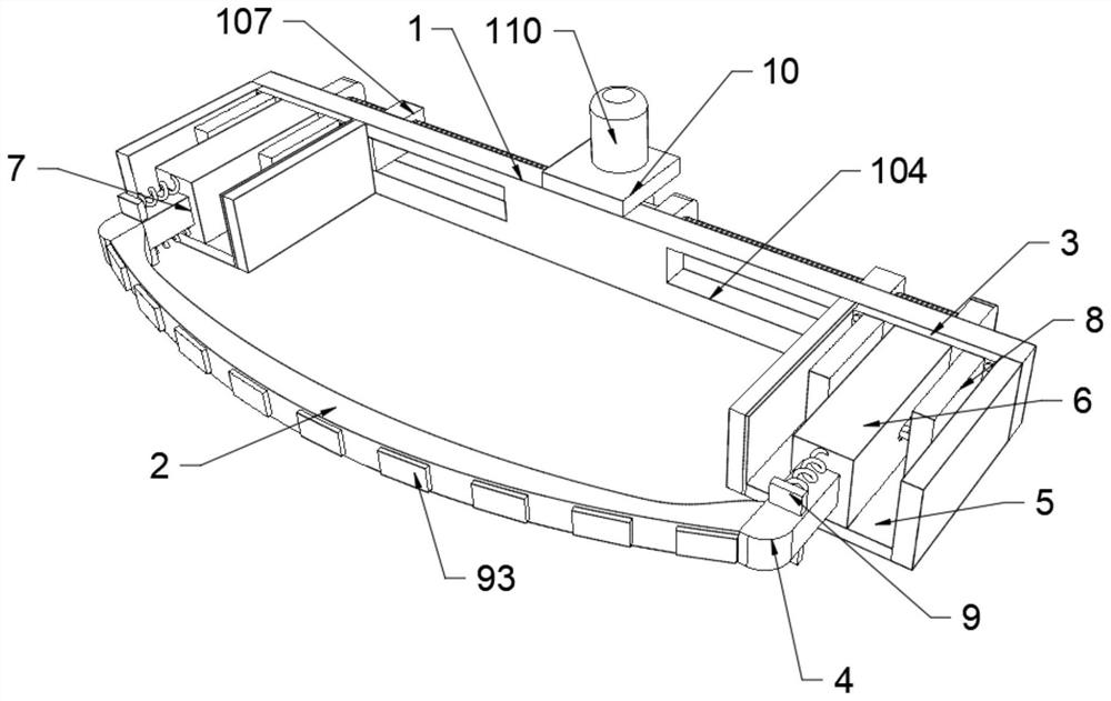
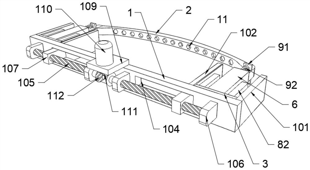
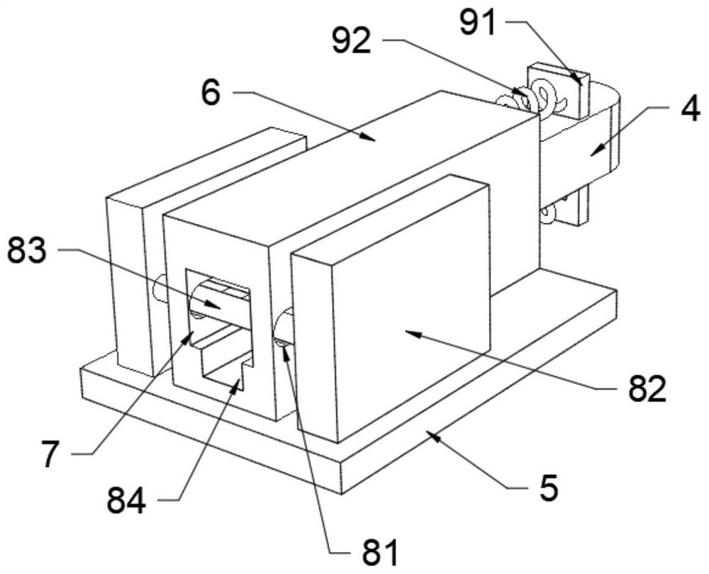
[0002] The anti-collision beam is a device used to reduce the absorption of collision energy when the vehicle is hit by a collision. It is composed of the main beam, the energy-absorbing box, and the mounting plate connected to the car. The main beam and the energy-absorbing box can effectively absorb when the vehicle collides at a low speed. Collision energy, to minimize the damage of the impact force to the longitudinal beams of the vehicle body, through which it can play its protective role on the vehicle; The impact energy is absorbed during a collision. However, this method is relatively simple. In order to protect the safety of the car and the occupants, a low-speed collision at the rear of the car will also cause damage to the anti-collision beam and the energy-absorbing box, which increases the cost of maintenance. In addition, the traditional energy-absorbing box is directly installed through bolts and mounting plates, but this fixing method is not stable enough in the event of a collision; therefore, we propose a new type of high-efficiency energy-absorbing automotive rear anti-collision beam

Method used


Image

  • Novel efficient energy absorption automobile rear anti-collision beam
  • Novel efficient energy absorption automobile rear anti-collision beam
  • Novel efficient energy absorption automobile rear anti-collision beam

Examples


Embodiment Construction

[0022] The following will clearly and completely describe the technical solutions in the embodiments of the present invention with reference to the accompanying drawings in the embodiments of the present invention. Obviously, the described embodiments are only some, not all, embodiments of the present invention. Based on the embodiments of the present invention, all other embodiments obtained by persons of ordinary skill in the art without making creative efforts belong to the protection scope of the present invention.

[0023] see figure 1 , figure 2 and image 3 , a new type of high-efficiency energy-absorbing automobile rear anti-collision beam in the illustration includes a mounting plate 1, an anti-collision beam body 2 and a connecting plate 3, and one side of the mounting plate 1 is provided with an anti-collision beam body 2, so The two ends of the anti-collision beam body 2 are symmetrically fixedly connected with sliding columns 4, and the side of the shown instal...


PUM


Abstract

The invention discloses a novel efficient energy absorption automobile rear anti-collision beam comprises a mounting plate, an anti-collision beam body and a connecting plate, the anti-collision beambody is arranged on one side of the mounting plate, sliding columns are symmetrically and fixedly connected to the two ends of the anti-collision beam body, and the connecting plate is symmetrically and fixedly mounted on the side, close to the anti-collision beam body, of the mounting plate through bolts; a bottom plate is fixedly connected to the bottom of the connecting plate, an energy absorption box is fixedly connected to the upper surface of the bottom plate, a sliding groove is formed in the energy absorption box, the outer surface of the sliding column is slidably connected with the sliding groove, a high-speed energy absorption device is fixedly connected to the upper surface of the bottom plate, and a low-speed energy absorption device is fixedly connected to the side, close tothe anti-collision beam, of the sliding column. According to the novel efficient energy absorption automobile rear anti-collision beam, low-speed collision and high-speed collision at the tail part ofan automobile can be respectively dealt with, and elements of the high-speed energy absorption device cannot be damaged during low-speed collision, so that the maintenance cost is reduced, and in addition, the fixing stability of the energy absorption box and the mounting plate is also improved.

Description

technical field [0001] The invention relates to the technical field of automobile rear anti-collision beams, in particular to a novel high-efficiency energy-absorbing automobile rear anti-collision beam. Background technique [0002] The anti-collision beam is a device used to reduce the absorption of collision energy when the vehicle is hit by a collision. It is composed of the main beam, the energy-absorbing box, and the mounting plate connected to the car. The main beam and the energy-absorbing box can effectively absorb when the vehicle collides at a low speed. Collision energy, to minimize the damage of the impact force to the longitudinal beams of the vehicle body, through which it can play its protective role on the vehicle; The impact energy is absorbed during a collision. However, this method is relatively simple. In order to protect the safety of the car and the occupants, a low-speed collision at the rear of the car will also cause damage to the anti-collision bea...

Claims


Application Information

Patent Timeline
Patent Type & Authority Applications(China)
IPC IPC(8): B60R19/18B60R19/24B60R19/34
CPCB60R19/18B60R19/24B60R19/34B60R2019/1806
Inventor 孔燕成徐园园方敬海
Owner NINGBO CHANGYANG MACHINERY IND CO LTD
Learn More