Auxiliary mounting device and mounting method for corrugated beam steel guardrail of bent road section

A technology for installing equipment and waveforms, applied to road safety devices, roads, roads, etc., can solve the problems of many operators, low installation efficiency, difficult docking, etc., to reduce weight and complexity, easy to carry, use, and operate Ease of use

Pending Publication Date: 2021-01-08
浦江伟婷建材有限公司
View PDF5 Cites 1 Cited by
  • Summary
  • Abstract
  • Description
  • Claims
  • Application Information

AI Technical Summary

Problems solved by technology

[0004] However, there is currently a lack of special bending construction equipment for corrugated beam steel guardrails. In the existing construction, the corrugated beam steel guardrails can only be bent manually, which not only consumes a lot of energy, requires many operators, but also has certain dangers. Simple tools such as levers are used to operate, which is difficult and dangerous
The existing installation equipment and installation methods cannot move the installation hole of the corrugated beam steel guardrail horizontally to the bracket at the front end of the column accurately, and can only move the corrugated beam steel guardrail roughly to the front end of the column. At this time, the corrugated beam steel guardrail There is a vertical distance between the installation center line and the installation hole on the bracket, which is difficult to connect, requires manual adjustments many times, complicated operation, and low installation efficiency

Method used


Image

  • Auxiliary mounting device and mounting method for corrugated beam steel guardrail of bent road section
  • Auxiliary mounting device and mounting method for corrugated beam steel guardrail of bent road section
  • Auxiliary mounting device and mounting method for corrugated beam steel guardrail of bent road section

Examples


Embodiment 1

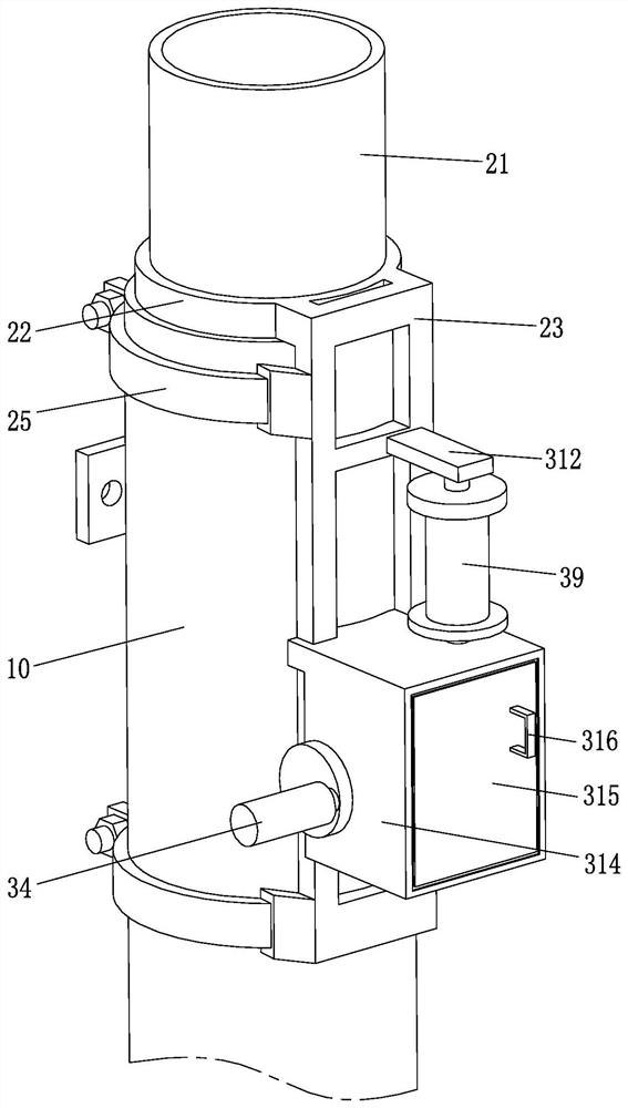
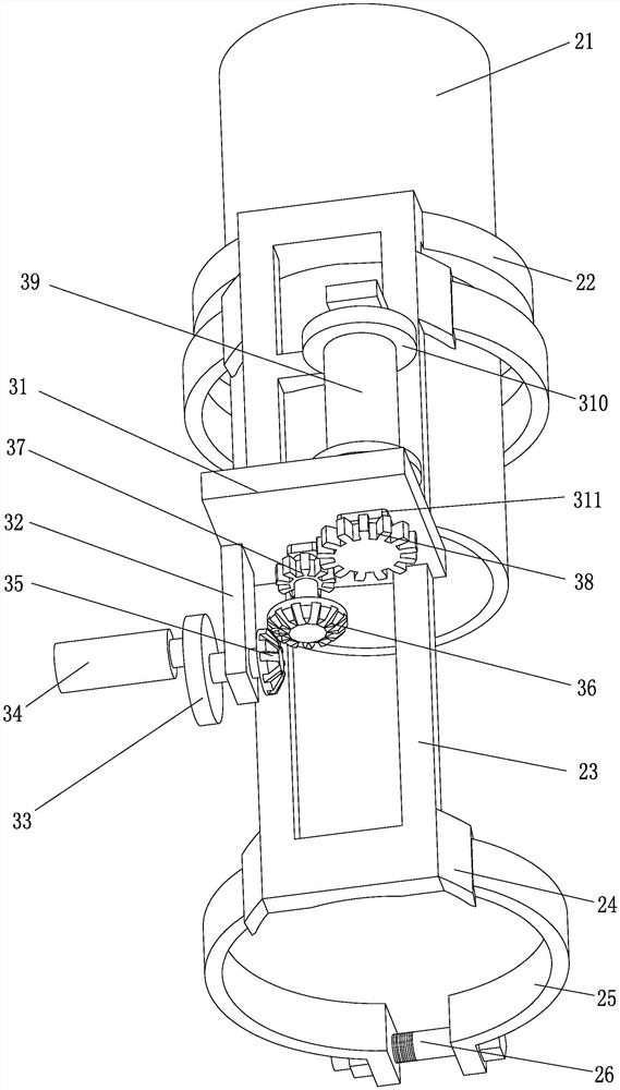
[0037] Such as Figure 2 to Figure 10 As shown, a wave beam steel guardrail auxiliary installation equipment for a curved road section of the present invention includes a wave beam steel guardrail pulling device 200, and the wave beam steel guardrail pulling device 200 includes an insertion rod 21, a support ring 22, a connecting frame 23, a To adjust the fastening assembly and the winding assembly, the insertion rod 21 is a hollow cylindrical shape in the center, and the insertion rod 21 is inserted into the hollow cylindrical hole in the center of the wave beam column 10 through the clearance fit of the shaft hole. In this embodiment, the outer surface of the insertion rod 21 The diameter is selected according to the inner diameter of the wave beam column 10, and the outer diameter of the inserting rod 21 is preferably 4-10 mm smaller than the inner diameter of the wave beam column 10. Due to the current specification "Wave Beam Steel Guardrail Part One: Two Wave Beam Steel G...

Embodiment 2

[0048] Such as Figure 2 to Figure 14As shown, on the basis of the structure in Embodiment 1, the corrugated beam steel guardrail clamp 300 in the auxiliary installation equipment for the corrugated beam steel guardrail of a curved section of the present invention includes a first splint 41, a splint hinge seat 42, a second splint 43, splint connecting block 44, splint connecting bolt 45, splint inner baffle plate 46, splint inner fixing seat 47 and pull ring 48, splint hinge seat 42 is located between the top of the first splint 41 and splint hinge seat 42, the first splint 41 and the top of the splint hinge seat 42 are hinged by the splint hinge seat 42, and a splint connecting block 44 is respectively fixed at the bottom contact of the first splint 41 and the splint hinge seat 42, and the two splint connecting blocks 44 pass through The splint connecting bolts 45 are connected, the inner side of the first splint 41 is fixed with a splint inner fixing seat 47 , the inside of...

Embodiment 3

[0053] Such as Figure 2 to Figure 14 As shown, the adjustable fastening assembly in the auxiliary installation equipment for the wave beam steel guardrail of a curved section of the present invention specifically includes a first hinge seat 24, a first sub-clamp 25 and a first long bolt 26, and the two first hinges The seat 24 is symmetrically arranged on the outside of the connecting frame 23, the rear end of the first sub-band 25 is hinged in the first hinged seat 24, and the front ends of the two first sub-bands 25 are respectively fixed with a hoop connection block 27, and the two The hoop connection blocks 27 are connected with the nuts through the first long bolt 26 and fixed by the hoop structure, which has simple structure, convenient operation and strong stability.


PUM


Abstract

The invention relates to the technical field of corrugated beam steel guardrail construction, and discloses an auxiliary mounting device and mounting method for a corrugated beam steel guardrail of abent road section. The auxiliary mounting device for a corrugated beam steel guardrail of a bent road section comprises a corrugated beam steel guardrail pulling device; the device comprises an inserting rod, a supporting ring, a connecting frame, adjustable fastening assemblies and a wire winding assembly, the inserting rod is a cylinder with the hollow center, and the inserting rod is inserted into a hollow cylindrical hole in the center of a corrugated beam stand column through a shaft hole in a clearance fit manner. A circle of annular supporting ring is fixed to the bottom end of the inserting rod, the connecting frame is vertically fixed to the rear portion of the supporting ring, the two adjustable fastening assemblies are connected to the front end of the connecting frame, one adjustable fastening assembly is located at the top of the front end of the connecting frame, and the other adjustable fastening assembly is located at the bottom of the front end of the connecting frame.The installation center line of a corrugated beam steel guardrail can be accurately in butt joint with installation holes in a bracket in the vertical direction, the installation efficiency is improved, and the equipment is convenient to use and carry.

Description

technical field [0001] The invention relates to the technical field of construction of a corrugated beam steel guardrail, in particular to an auxiliary installation device and an installation method for a corrugated beam steel guardrail in a curved road section. Background technique [0002] The road safety guardrail is a longitudinal energy-absorbing mechanism that absorbs collision energy through self-deformation or vehicle climbing, thereby changing the form and direction of the vehicle, preventing the vehicle from driving out of the driving lane or entering the opposite lane, and can reduce the degree of driver injury and protect the road. side objects. Wave beam steel guardrail is currently the most widely used form of safety guardrail, which includes two wave beam steel guardrails and three wave beam steel guardrails. [0003] There will inevitably be curved road sections in the construction of highway safety guardrails, for example, as shown in the attached manual f...

Claims


Application Information

Patent Timeline
Patent Type & Authority Applications(China)
IPC IPC(8): E01F15/02E01F15/04
CPCE01F15/02E01F15/04E01F15/0484
Inventor 汪玉洁
Owner 浦江伟婷建材有限公司
Why Eureka
Try Eureka