Monitoring method and device for real-time working condition of catalytic reforming device

A technology of catalytic reforming and real-time working conditions, applied in special data processing applications, instruments, complex mathematical operations, etc., can solve problems such as flooding of alarms

Pending Publication Date: 2021-01-08
ZHEJIANG SUPCON TECH +1
View PDF0 Cites 7 Cited by
  • Summary
  • Abstract
  • Description
  • Claims
  • Application Information

AI Technical Summary

Problems solved by technology

[0003] At present, the catalytic reforming unit mainly relies on the conventional DCS monitoring and alarm system for real-time monitoring of working conditions. Its main defect lies in the use of fixed limit alarms. Since the fixed limits are often set artificially, if the setting is impr

Method used


Image

  • Monitoring method and device for real-time working condition of catalytic reforming device
  • Monitoring method and device for real-time working condition of catalytic reforming device
  • Monitoring method and device for real-time working condition of catalytic reforming device

Examples


Embodiment 1

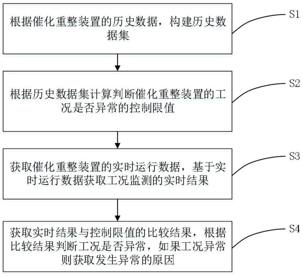
[0065] Such as figure 1 As shown, the present invention proposes a monitoring method for the real-time working condition of catalytic reforming unit, comprising:

[0066] S1: Construct a historical data set based on the historical data of the catalytic reformer.

[0067] In this embodiment, the operating data of the catalytic reforming device in each process section is collected through the deployed instrumentation device and data acquisition device, and the operating data includes reaction condition data, reaction inlet and reaction outlet of the catalytic reforming device component data. Then the collected data is mapped to the calculation model according to the corresponding device tag number, so that the collected data can be processed and calculated later. After the operating data is collected, the operating data must first be preprocessed to filter out invalid data in the operating data, such as outlier data generated by skipping tables, dead line data generated due to...

Embodiment 2

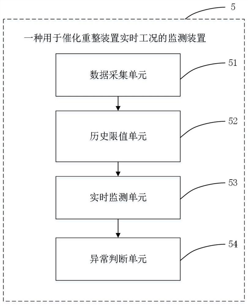
[0127] Such as image 3 As shown, the present invention also proposes a monitoring device 5 for the real-time working condition of the catalytic reformer, comprising:

[0128] Data collection unit 51: for constructing a historical data set according to the historical data of the catalytic reforming unit;

[0129] Historical limit value unit 52: used to calculate the control limit value for judging whether the working condition of the catalytic reformer is abnormal according to the historical data set;

[0130] Real-time monitoring unit 53: used to obtain real-time operating data of the catalytic reformer, and obtain real-time results of working condition monitoring based on the real-time operating data;

[0131] Abnormality judging unit 54: used to obtain the comparison result between the real-time result and the control limit, judge whether the working condition is abnormal according to the comparison result, and obtain the cause of the abnormality if the working condition i...


PUM


Abstract

The invention provides a monitoring method for real-time working conditions of a catalytic reforming device, wherein the method comprises the steps: constructing a historical data set according to historical data of the catalytic reforming device; calculating a control limit value for judging whether the working condition of the catalytic reforming device is abnormal or not according to the historical data set; acquiring real-time operation data of the catalytic reforming device, and acquiring a real-time result of working condition monitoring based on the real-time operation data; obtaining acomparison result of the real-time result and the control limit value, judging whether the working condition is abnormal or not according to the comparison result, and obtaining an abnormal reason ifthe working condition is abnormal; and directly analyzing and calculating a control limit value for judging whether the working condition is abnormal or not from the historical data, and judging thereason of the abnormal working condition by constructing a directed graph. Compared with a mode of setting fixed limitation purely according to experience, the abnormal condition of the real-time working condition can be judged more comprehensively and quickly, and the defect of improper setting of the fixed limitation is avoided.

Description

technical field [0001] The invention belongs to the field of petrochemical condition monitoring, and in particular relates to a monitoring method and device for real-time working condition of a catalytic reforming device. Background technique [0002] The catalytic reforming unit is one of the main units of petroleum refining. Its main process is to convert naphtha into aromatics and high-octane gasoline through complex catalytic reactions and by-product hydrogen. Most of the products and production units have flammable, flammable To ensure the smooth and safe operation of the reforming unit and product quality, it is necessary to monitor the abnormal conditions of the working conditions in real time and remind the operators to intervene to avoid safety accidents. [0003] At present, the catalytic reforming unit mainly relies on the conventional DCS monitoring and alarm system for real-time monitoring of working conditions. Its main defect lies in the use of fixed limit ala...

Claims


Application Information

Patent Timeline
IPC IPC(8): G06F16/2458G06F16/901G06F17/18
CPCG06F16/2465G06F16/9024G06F17/18
Inventor 刘凯娄海川林雪茹韦时斌查百惠
Owner ZHEJIANG SUPCON TECH
Why Eureka
Try Eureka