Novel bypass auxiliary circuit breaker replacement device

A technology of auxiliary devices and circuit breakers, applied in the direction of switchgear, electrical components, etc., can solve problems such as safety accidents, large losses, and affecting the normal operation of power distribution lines, and achieve the effect of avoiding falling off and preventing electric shock

Pending Publication Date: 2021-01-08
STATE GRID SHANDONG ELECTRIC POWER COMPANY WEIFANG POWER SUPPLY +1
View PDF3 Cites 0 Cited by
  • Summary
  • Abstract
  • Description
  • Claims
  • Application Information

AI Technical Summary

Problems solved by technology

If there is an abnormality, it will affect the normal operation of the distribution line and even cause a safety accident
[0003] At present, the replacement of the circuit breaker requires

Method used


Image

  • Novel bypass auxiliary circuit breaker replacement device
  • Novel bypass auxiliary circuit breaker replacement device
  • Novel bypass auxiliary circuit breaker replacement device

Examples


Embodiment Construction

[0022] The present invention will be described in further detail below in conjunction with specific examples. It should be understood that the specific embodiments described here are only used to explain the present invention, not to limit the present invention.

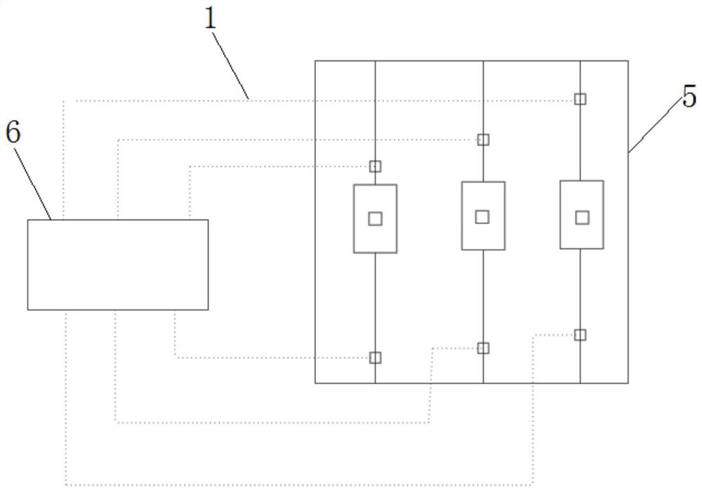
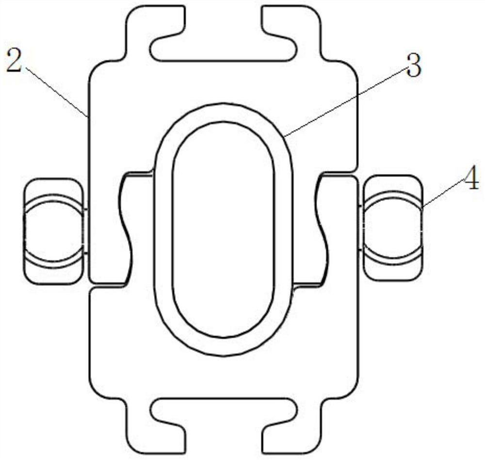
[0023] refer to Figure 1-5 As shown, a new bypass auxiliary circuit breaker replacement device includes a new bypass auxiliary device body 1, a low-voltage switch cabinet 5, a load switch 6 and a fixing mechanism; the two ends of the new bypass auxiliary body 1 are respectively fixed by The mechanism is set at the busbar and outlet side of the low-voltage switchgear 5, and the load switch 6 is connected to the body 1 of the new bypass auxiliary device; the fixing mechanism includes a clamping mechanism 2, a threading cylinder 3 and a locking mechanism 4; The threading cylinder 3 is set in the hollow chamber of the clamping mechanism 2, and the new bypass auxiliary device body 1 is arranged inside, and the locking m...


PUM


Abstract

The invention discloses a novel bypass auxiliary circuit breaker replacement device. The device comprises a novel bypass auxiliary device body and a fixing mechanism. The two ends of the novel bypassauxiliary body are arranged at a busbar and an outgoing line side of a low-voltage switch cabinet through fixing mechanisms respectively. The fixing mechanism comprises a clamping mechanism, a threading cylinder and a locking mechanism; the threading cylinder is arranged in a hollow cavity of the clamping mechanism, the novel bypass auxiliary device body is arranged in the threading cylinder, andthe locking mechanism is arranged at the two sides of the clamping mechanism and fixes the threading cylinder to a busbar and a wire outlet side of a low-voltage switch cabinet. The problem of power failure is solved, and the power failure duration during maintenance can be reduced to zero; the novel bypass auxiliary device body is prevented from falling off of the busbar and the wire outlet sideof the low-voltage cabinet, and the risk of electric shock of an operator is prevented.

Description


Claims


Application Information

Patent Timeline
Owner STATE GRID SHANDONG ELECTRIC POWER COMPANY WEIFANG POWER SUPPLY
Why Eureka
Try Eureka