Bonnet latch device

A technology of engine hood and latch device, which is applied in the application of building locks, vehicle locks, locks, etc. It can solve the problems of easy warping and deformation of the bottom plate, poor closing of the engine hood, relative position deviation between the latch and the ratchet, etc. To achieve the effect of high undertaking effect

Active Publication Date: 2021-01-08
MITSUI KINZOKU ACT
View PDF15 Cites 0 Cited by
  • Summary
  • Abstract
  • Description
  • Claims
  • Application Information

AI Technical Summary

Problems solved by technology

[0006] In the conventional hood latch device, since the bottom of the striker entry passage of the bottom plate bears most of the closing movement force (closing energy) of the striker, an excessive load is concentrated on the bottom, and the bottom plate is easily warped and deformed. , the relative position of the latch and the ratchet is shifted, sometimes resulting in poor closing and opening of the hood
[0007] In Patent Document 1, a separate reinforcement member is attached to the bottom of the striker entry passage, but in a vehicle (especially an SUV type vehicle) using a large and heavy hood, the movement force due to the closing of the striker increases dramatically. , so it is difficult to prevent the warping and deformation of the bottom plate

Method used


Image

  • Bonnet latch device
  • Bonnet latch device
  • Bonnet latch device

Examples


Embodiment Construction

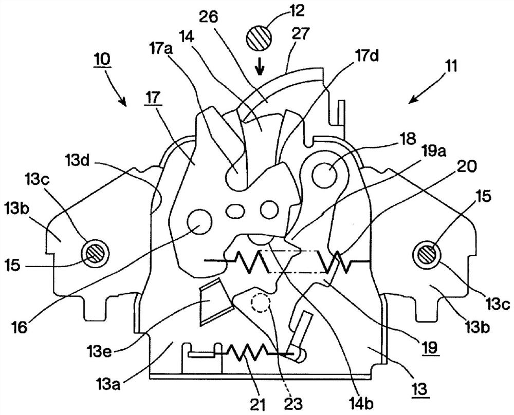
[0035] One embodiment of the present invention will be described based on the drawings. figure 1 The front of the hood latch device 10 for an engine hood of this invention is shown. In most vehicles, the engine room is disposed on the front side of the vehicle, and an end (base end) of a typical hood (not shown) covering the engine room is equiaxially fixed to the vehicle body by a hinge. The hood latch device 10 includes a latch unit 11 fixed to the front end of the vehicle body, and a striker 12 fixed to the front end (rotational end) of the hood.

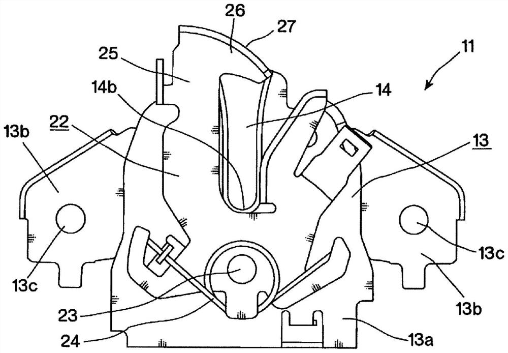
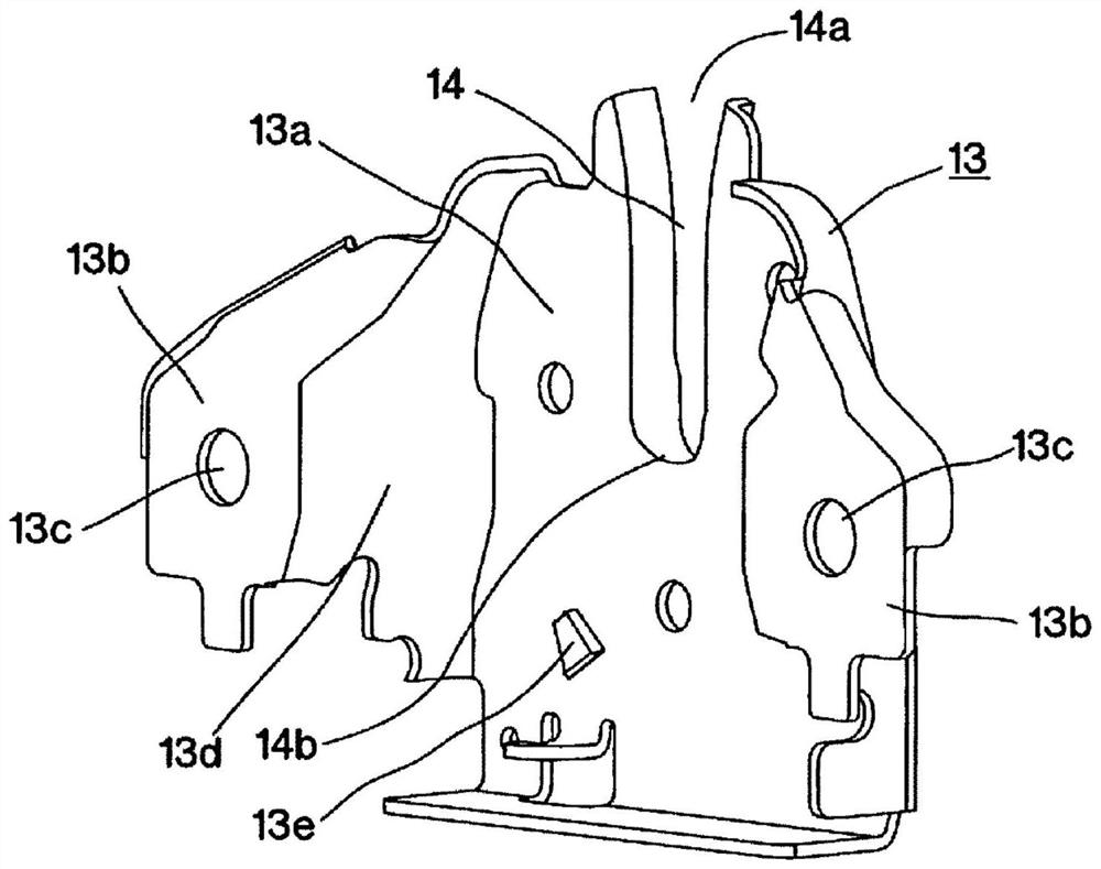
[0036] The latch unit 11 includes a metal bottom plate 13 . Bottom plate 13 is stamping molding product, as Figure 1 ~ Figure 3 As shown, a central plate 13a and left and right fixing plates 13b are provided. A striker entry passage 14 is formed in the upper center of the center plate 13a. The striker entry passage 14 is in the shape of a longitudinal U, with an opening 14a at the top and a bottom wall 14b at the bottom. Af...


PUM


Abstract

According to the present invention, to distribute and bear the increasing force of the door closing movement of a striker 12, a latch unit 11 comprises: a latch 17 that engages the striker 12 and thereby rotates from an unlatched position past a latched position to an over-rotated position; and a ratchet 19 that engages the latch 17 as returned from the over-rotated position to the latched position by the elastic force of a latch spring 20 and keeps the latch 17 and the striker engaged. The latch unit 11 comprises a plurality of support members that contact the latch 17 when the latch 17 has reached the over-rotated position and thereby bear the force of the over-rotation of the latch 17. The support members are distributed in at least two of the four quadrants that are demarcated by a horizontal line C and a vertical line B that pass through the rotational center of a latch shaft 16.

Description

technical field [0001] The present invention relates to a latch device for a hood (hood), and more particularly, to a hood latch device with improved strength. Background technique [0002] As in Patent Document 1, a conventional hood latch device includes a striker attached to a hood, and a latch unit attached to a vehicle body and engaged with the striker. A latch engaged with the striker and a ratchet engaged with the latch to maintain the engagement between the latch and the striker are fixed to the shaft on the bottom plate of the latch unit. A striker entry passage is provided on the bottom plate. The entry passage of the striker is in the shape of a bottomed U with an open upper part. [0003] When the engine hood is closed, the striker moves downward, enters the striker entry passage, and abuts against the striker engagement groove of the latch. By this abutment, the latch over-rotates from the unlocked position beyond the latched position against the elastic forc...

Claims


Application Information

Patent Timeline
IPC IPC(8): E05B83/24B62D25/12
CPCE05B83/24E05B85/26B62D25/12E05B79/04E05B83/243E05B85/243
Inventor 宫川正纯金子俊哉佐藤久美子
Owner MITSUI KINZOKU ACT
Why Eureka
Try Eureka