A dump truck rollover protection structure and cab rops skeleton
A technology for protecting structures and dump trucks, which is applied to the superstructure, superstructure, and subassembly of trucks, etc., can solve the problems of increasing the design cycle, restricting drivers, and potential safety hazards, so as to simplify the production process, The effect of improving the field of view and improving the safety performance
- Summary
- Abstract
- Description
- Claims
- Application Information
AI Technical Summary
Problems solved by technology
Method used
Image

Examples
Embodiment 1
[0044] like Image 6 As shown, a cab ROPS framework 1 includes a top load beam 11, a C-pillar 13, a D-pillar 14, a bottom load beam 15, a top C-shaped frame 16, a B-pillar 17, and a bottom C-shaped frame 18. 11. C-pillar 13, D-pillar 14, and bottom load-bearing beam 15 form a load-bearing component, and the top C-shaped frame 16, B-pillar 17, and bottom C-shaped frame 18 jointly constitute a functional component;
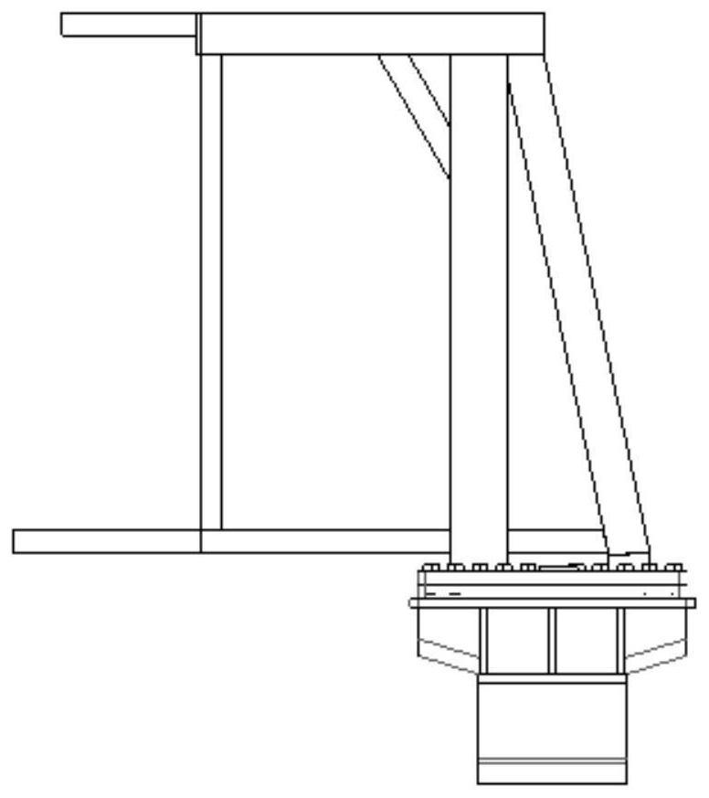
[0045] The ROPS frame 1 of the cab uses the C-pillar and the D-pillar as load-bearing columns, and the top load-bearing beam 11 and the bottom load-bearing beam 15 are both square frame structures and arranged horizontally; the C-pillar 13 is vertically arranged, and the top of the C-pillar is connected to the top load-bearing beam 11 At the bottom of the outer corner, the bottom of the C-pillar is connected to the inner corner of the bottom load-bearing beam 15; the D-pillar is installed obliquely, and the top of the D-pillar is connected to the bottom of the outer...
Embodiment 2
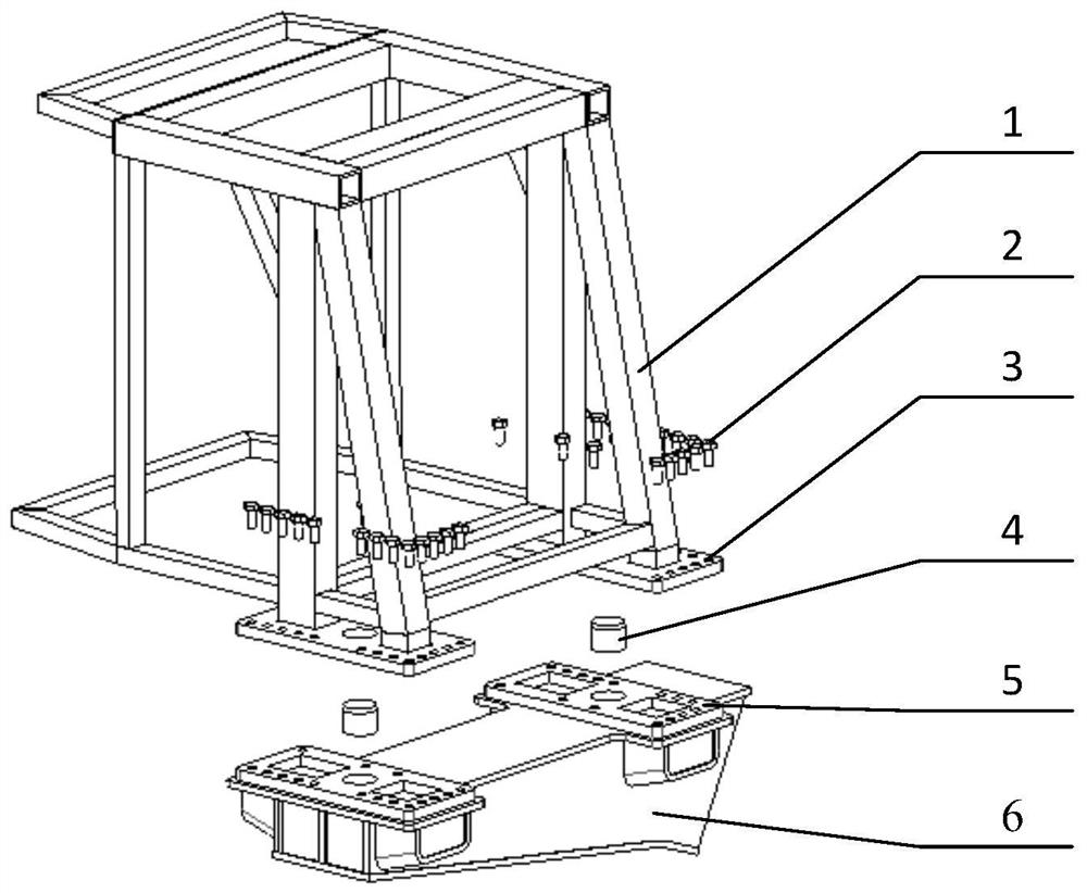
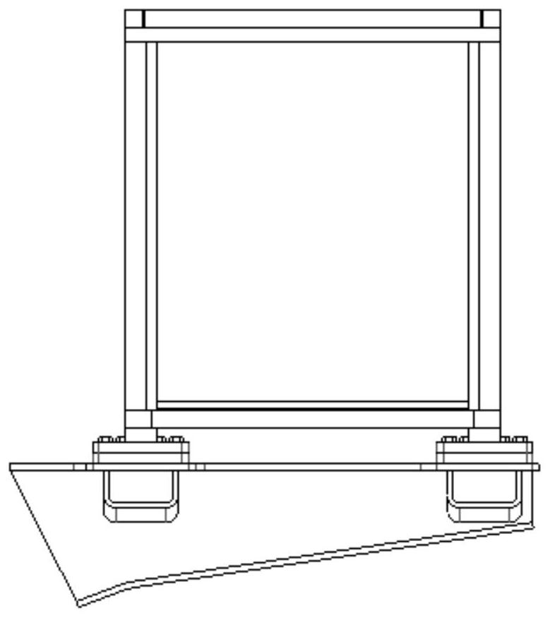
[0050] A dump truck rollover protection structure, comprising an upper mounting base 3, a limit structure, a lower mounting base 5, a rear connecting beam 6 and the above-mentioned cab ROPS framework 1;
[0051] The bottom ends of the C-pillar and the D-pillar are fixed on the upper mounting seat 3, and the C-pillar, the D-pillar and the upper mounting seat form a triangular structure;
[0052] The lower mounting seat 5 is fixed on the corresponding position on the upper surface of the rear connecting beam 6;
[0053] The corresponding positions of the upper mounting base 3 and the lower mounting base 5 are provided with limiting structures for limiting the horizontal rotation of the cab relative to the vehicle frame, and bolt holes for installing fixing bolts;
[0054] The cab ROPS frame 1 is fixed together with the upper mounting base 3, and the rear connecting beam 6 is fixed together with the lower mounting base 5. Positioning and installation are carried out through the l...
PUM
 Abstract
Description
Claims
Application Information
 - R&D
- Intellectual Property
- Life Sciences
- Materials
- Tech Scout
- Unparalleled Data Quality
- Higher Quality Content
- 60% Fewer Hallucinations
Browse by: Latest US Patents, China's latest patents, Technical Efficacy Thesaurus, Application Domain, Technology Topic, Popular Technical Reports.
© 2025 PatSnap. All rights reserved.Legal|Privacy policy|Modern Slavery Act Transparency Statement|Sitemap|About US| Contact US: help@patsnap.com