Electrical equipment precise installation intelligent operation platform

A technology of intelligent operation and electrical equipment, applied in the direction of lifting equipment safety device, lifting device, etc., can solve the problems that the operating platform cannot be self-locked, the supporting feet can be manually pulled out manually, etc. The effect of preventing overturning

Active Publication Date: 2021-01-12
国网山东省电力公司建设公司 +2
View PDF8 Cites 0 Cited by
  • Summary
  • Abstract
  • Description
  • Claims
  • Application Information

AI Technical Summary

Problems solved by technology

[0005] Aiming at the deficiencies of the prior art, the present invention provides an intelligent operation platform for precise installation of electrical equipment, which solves the problem that the operation platform cannot be self-locked when an accident occurs, and the supporting legs need to be manually pulled out

Method used


Image

  • Electrical equipment precise installation intelligent operation platform
  • Electrical equipment precise installation intelligent operation platform
  • Electrical equipment precise installation intelligent operation platform

Examples


Embodiment 1

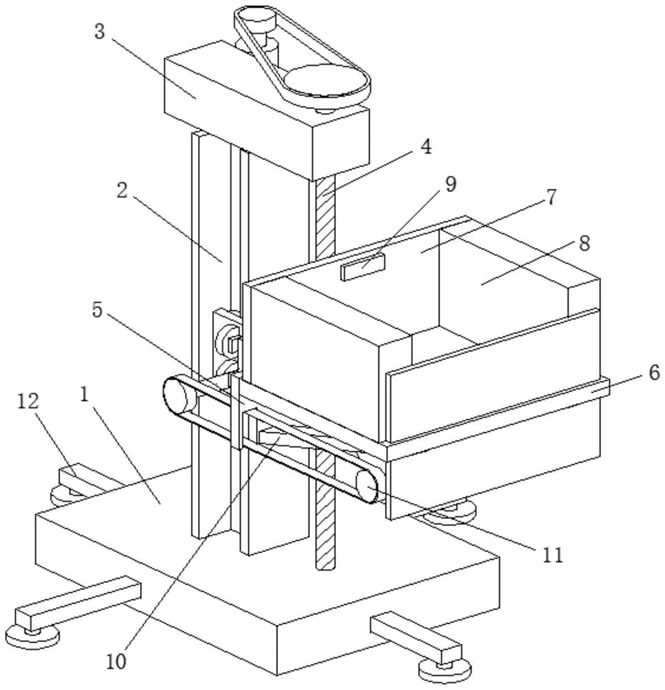
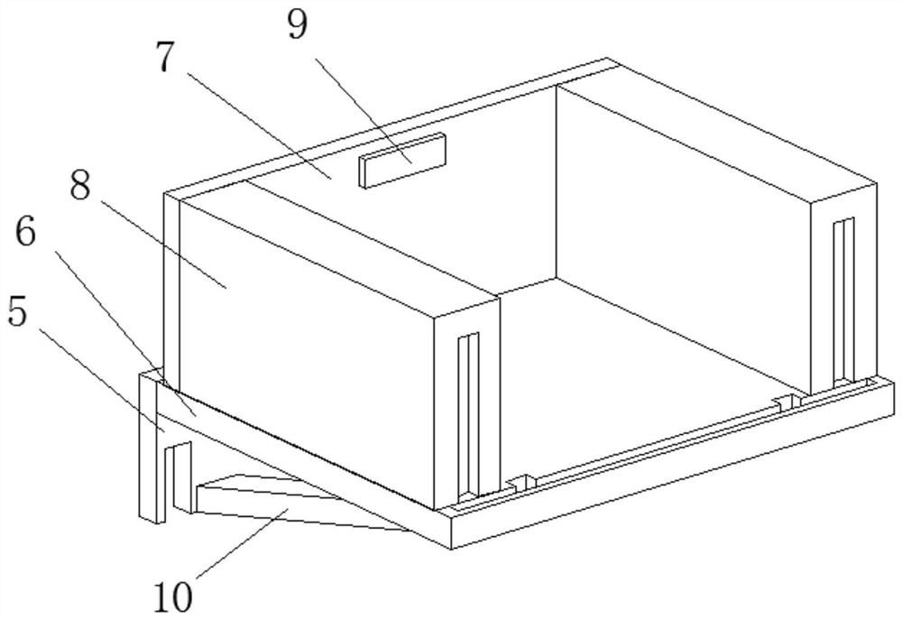
[0034] An intelligent operation platform for precise installation of electrical equipment, such as Figure 1-Figure 6 As shown, including the base 1, the top of the base 1 is welded with an I-beam 2, the top of the I-beam 2 is welded with a mounting block 3, the bottom of the mounting block 3 is provided with a lifting mechanism 4, and the right side of the lifting mechanism 4 is set There is connecting plate 5, and the right side of connecting plate 5 is welded with supporting plate 6, and the top of supporting plate 6 is welded with baffle plate 7 and toolbox 8 respectively, and toolbox 8 is positioned at the right side of baffle plate 7, and the right side of baffle plate 7 The side is connected with a control panel 9 by bolts, a support rod 10 is welded between the connection plate 5 and the support plate 6 , the lower surface of the support rod 10 is provided with a protection mechanism 11 , and the inside of the base 1 is provided with a support mechanism 12 .

[0035] I...

Embodiment 2

[0041] Such as Figure 5-Figure 8 As shown, the rear portion of the rotating shaft 111 is clamped and fixed with the axial center of the second roller 472, the surface of the rotating shaft 111 is rotationally connected with the inner wall of the moving plate 47, and the axial center of the second sprocket 113 and the transmission gear 116 are respectively connected with the support The front part and the rear part of block 114 are rotatably connected, the surface of transmission gear 116 and the surface of teeth 117 are meshed with each other, and rotating shaft 111 is connected with the No. The protective mechanism 11 drives the protective fence 115 to rise, and when the second roller 472 descends, the protective fence 115 also descends. When the rotating shaft 111 is connected with the second roller 472 on the left side, the second roller 472 rises and the protective fence 115 will descend, resulting in Cannot play a protective role.

[0042] It is worth noting that the su...


PUM


Abstract

The invention relates to the technical field of operation platforms and discloses an electrical equipment precise installation intelligent operation platform which comprises a base; I-shaped steel iswelded to the top of the base; an installation block is welded to the top of the I-shaped steel; a lifting mechanism is arranged at the bottom of the installation block; and a connecting plate is arranged on the right side of the lifting mechanism; a supporting plate is welded to the right side of the connecting plate; a baffle plate and a tool box are welded to the top of the supporting plate; acontrol panel is connected to the right side of the baffle plate through bolts; a protection mechanism is arranged on the lower surface of the supporting rod; and a supporting mechanism is arranged inthe base. By adopting the electrical equipment precise installation intelligent operation platform disclosed by the invention, lifting of the operation platform can be achieved through the lifting mechanism; threads can perform self-locking, so that when a power source goes wrong, safety accidents of workers are prevented through self-locking of the threads; and for the supporting mechanism, supporting legs can automatically extend out without manual operation of the workers and folding are more convenient and faster in unfolding, so that application and popularization are better facilitated.

Description

technical field [0001] The invention relates to the technical field of operation platforms, in particular to an intelligent operation platform for precise installation of electrical equipment. Background technique [0002] When carrying out precision installation operations of electrical equipment, it is often necessary to use an operating platform to facilitate the installation of electrical equipment. [0003] The operating platforms in the current market are basically driven by hydraulic cylinders. When an accident occurs in the hydraulic cylinder, there is no self-locking device, which has hidden dangers in installation, and the supporting feet under the operating platform are pulled out manually one by one, which is very troublesome. It will also increase the labor intensity of workers, so an intelligent operation platform for precise installation of electrical equipment is proposed to solve the above-mentioned problems. Contents of the invention [0004] (1) Solved ...

Claims


Application Information

Patent Timeline
Patent Type & Authority Applications(China)
IPC IPC(8): B66F11/00B66F13/00B66F17/00
CPCB66F11/00B66F13/00B66F17/00
Inventor 姜兆庆安重霖王钦刘忠声商志宙段晓明李本浩张兴李金金
Owner 国网山东省电力公司建设公司
Why Eureka
Try Eureka