
Steel structure frame type tower crane foundation

A technology of steel structure frame and tower crane, applied in the direction of infrastructure engineering, construction, etc., can solve the problems of increasing workload, structural impact, occupying compartment area, etc., and achieve the effect of avoiding loss and damage

Pending Publication Date: 2021-01-12
CHANGDE RONGCHENG MACHINERY CO LTD
View PDF1 Cites 0 Cited by
  • Summary
  • Abstract
  • Description
  • Claims
  • Application Information

AI Technical Summary

Problems solved by technology

[0003] Patent No. CN203022020U provides a steel structure frame tower crane foundation, which solves the problem that the main concrete foundation unit, transition concrete foundation unit, and end concrete foundation unit need special special molds in the process of pouring concrete, and a large number of The lack of mold making also solves the substantive technical problems of taking up too much space in the carriage during supply and transportation, the total weight is too heavy, and high freight costs are required for long-distance transportation. It has novel structure, high safety performance, Easy disassembly and transportation
[0004] However, when the patent is fixedly connected during use, the position of the basic unit deviates from the expected one, which affects the fixing of the structure and increases the workload; at the same time, due to the large number of bolts and other parts during transportation, Easy to cause loss and damage during transportation

Method used


Image

  • Steel structure frame type tower crane foundation
  • Steel structure frame type tower crane foundation
  • Steel structure frame type tower crane foundation

Examples


Embodiment Construction

[0025] The following will clearly and completely describe the technical solutions in the embodiments of the present invention with reference to the accompanying drawings in the embodiments of the present invention. Obviously, the described embodiments are only some, not all, embodiments of the present invention. Based on the embodiments of the present invention, all other embodiments obtained by persons of ordinary skill in the art without making creative efforts belong to the protection scope of the present invention.

[0026] In the description of the present invention, it should be noted that the terms "center", "upper", "lower", "left", "right", "vertical", "horizontal", "inner", "outer" etc. The indicated orientation or positional relationship is based on the orientation or positional relationship shown in the drawings, and is only for the convenience of describing the present invention and simplifying the description, rather than indicating or implying that the referred d...


PUM


Abstract

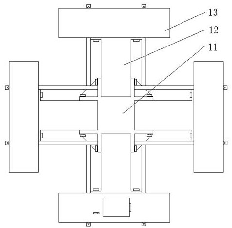
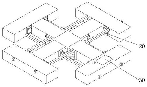
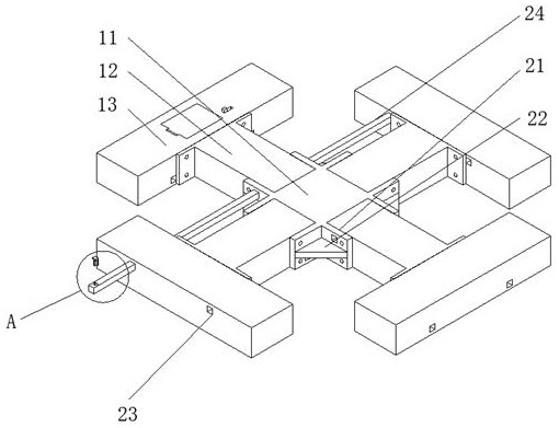
The invention discloses a steel structure frame type tower crane foundation. The steel structure frame type tower crane foundation comprises a main body, a fixing mechanism and a storage mechanism, the main body comprises a main concrete foundation unit, and the outer wall of the main concrete foundation unit is connected with a transition concrete foundation unit. By arranging fixing plates and connecting rods, the transition concrete foundation unit is attached to the main concrete foundation unit along the position between every two parallel and adjacent fixing plates, an end concrete foundation unit is arranged at one end of the transition concrete foundation unit, the connecting rods sequentially penetrate through the end concrete foundation units, the transition concrete foundation unit and connecting grooves in the fixing plates, buckles are attached to the inner walls of the connecting rods to fix the connecting rods, thus pre-fixing of the tower crane foundation is completed,primary pre-fixing can be conveniently conducted when the tower crane foundation is fixedly connected, and the influence on the connection due to the position deviation of the foundation units is avoided.

Description

technical field [0001] The invention relates to the field of tower cranes, in particular to a steel structure frame tower crane foundation. Background technique [0002] Tower crane is the most commonly used lifting equipment on construction sites, also known as "tower crane". It is used to lift steel bars, Raw materials for construction such as wood corrugated, concrete, and steel pipes, tower cranes are an indispensable equipment on the construction site. [0003] Patent No. CN203022020U provides a steel structure frame tower crane foundation, which solves the problem that the main concrete foundation unit, transition concrete foundation unit, and end concrete foundation unit need special special molds in the process of pouring concrete, and a large number of The lack of mold making also solves the substantive technical problems of taking up too much space in the carriage during supply and transportation, the total weight is too heavy, and high freight costs are required ...

Claims


Application Information

Patent Timeline
IPC IPC(8): E02D27/42E02D27/44
CPCE02D27/42E02D27/44
Inventor 周游李伟张力
Owner CHANGDE RONGCHENG MACHINERY CO LTD
Learn More