
Ratchet push-pull self-locking electric connector

An electric connector, push-pull self-locking technology, applied in the direction of connection and connection device components, circuits, etc., can solve problems such as constraints, increased installation difficulty, locking and unlocking process operation complexity, etc., to achieve ingenious structure, self-locking The effect of stable performance and convenient plug-in operation

Pending Publication Date: 2021-01-12
CHENGDU HONGMING ELECTRONICS CO LTD
View PDF0 Cites 0 Cited by
  • Summary
  • Abstract
  • Description
  • Claims
  • Application Information

AI Technical Summary

Problems solved by technology

After the plug is inserted into the socket, it will be affected by the vibration of external equipment during use, which will cause the plug to withdraw from the socket. The traditional method is to lock the connection with threads, buckles or snap locks, which often requires additional locking parts. This increases the difficulty of installation, and sometimes causes no dedicated space to install the locking structure. The locking and unlocking process is relatively complicated to operate, and is easily restricted by the assembly environment.

Method used


Image

  • Ratchet push-pull self-locking electric connector
  • Ratchet push-pull self-locking electric connector
  • Ratchet push-pull self-locking electric connector

Examples


Embodiment

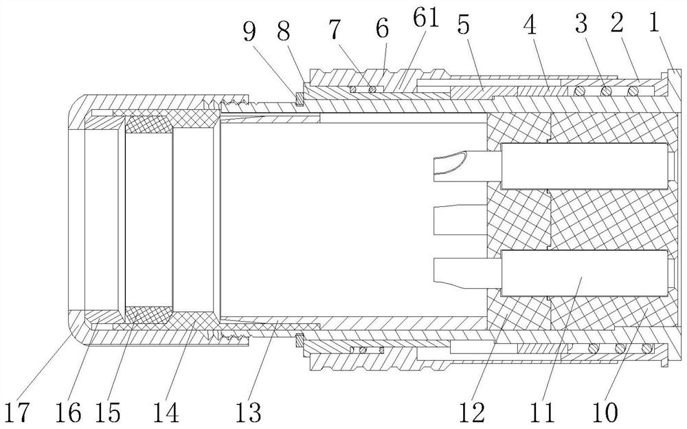
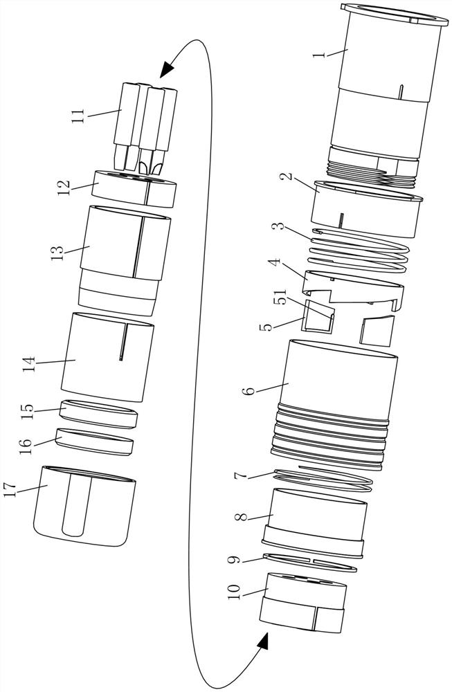
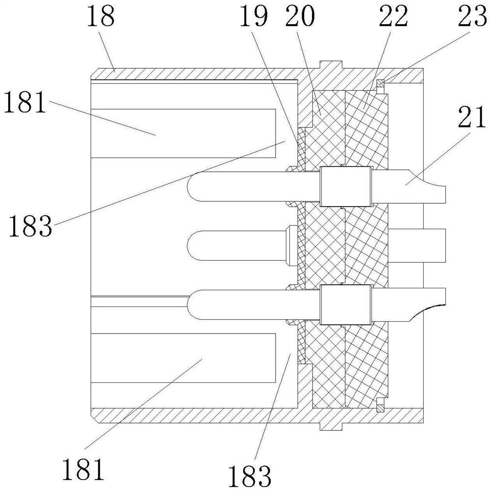
[0038] like Figure 1 to Figure 15 As shown, a ratchet push-pull self-locking electrical connector includes a plug assembly and a socket assembly. The plug assembly includes a head shell 1 and a tail nut 17 connected to the head shell 1. The front end of the head shell 1 is movably fitted with a locking ring. 2. A ratchet 4 is movably installed on the locking ring 2, and the ratchet 4 can move axially between the head housing 1 and the locking ring 2, such as figure 1 As shown, the ratchet 4 moves axially on the locking ring 2 , and at the same time the ratchet 4 can drive the locking ring 2 to rotate outside the head housing 1 . like Figure 7 , Figure 8As shown, the locking ring 2 has a limit chute A201, and the outer wall of the ratchet 4 has a limit slider A41 corresponding to the limit chute A201. When assembling, the limit slider A41 of the ratchet 4 is installed on the lock. In the limit chute A201 of the tight ring 2, when the ratchet 4 moves axially in the lock ri...


PUM


Abstract

The invention discloses a ratchet push-pull self-locking electric connector which comprises a plug assembly and a socket assembly. The front end of a plug shell is movably sleeved with a locking ring,a ratchet is movably installed on the locking ring, a positioning block is installed on the outer side wall of a head shell, a positioning sleeve is fixed to the outer side wall of the rear end of the head shell, and the outer portion of the positioning sleeve and the outer portion of the locking ring are sleeved with push-pull rings. A positioning block matching groove is formed in a push-pull gear of the push-pull ring, the ratchet wheel is provided with four continuous ratchets, the socket assembly comprises a seat shell and a needle insulator, a long-strip constraint block is arranged onthe inner side wall of the seat shell, a locking bottom plate is further arranged on the inner side wall of the seat shell, and a locking gap is formed between the end of the long-strip constraint block and the locking bottom plate. The front end of the locking ring is provided with an outwards-turned round step plate, and the outwards-turned round step plate is provided with a restraining edge. Locking and unlocking operations are jointly realized by combining a plug-in position relationship between the plug and the socket and a position relationship that the push-pull ring pushes the ratchetwheel, the purpose of push-pull and direct-plug operation self-locking is realized, and the electric connector has the advantages of long service life, reliable performance and the like.

Description

technical field [0001] The invention relates to an electrical connector, in particular to a ratchet push-pull self-locking electrical connector. Background technique [0002] The electrical connector includes a plug and a socket, which is a combined structure that realizes the electrical insertion of the plug and the socket. After the plug is inserted into the socket, it will be affected by the vibration of external equipment during use, which will cause the plug to withdraw from the socket. The traditional method is to lock the connection with threads, buckles or snap locks, which often requires additional locking parts. This increases the difficulty of installation, and sometimes causes no dedicated space to install the locking structure. The operation of the locking and unlocking process is relatively complicated, and is easily restricted by the assembly environment. In recent years, the straight-plug fast push-pull self-locking method has become a research direction, so...

Claims


Application Information

Patent Timeline
IPC IPC(8): H01R13/639
CPCH01R13/639
Inventor 余睿刘向阳吴旭娇沈靖舒高兰陈松方莲肖雨辰黄婉秋郭安迪张晓阳
Owner CHENGDU HONGMING ELECTRONICS CO LTD
Learn More