Municipal pipeline based on liquid nitrogen conveying and provided with plugging device

A plugging device and technology for municipal pipelines, applied in the direction of pipe components, mechanical equipment, sealing surface connections, etc., can solve problems such as pipeline blockage, inconvenient operation, time-consuming and manual labor, and achieve integrity and good sealing The effect of blocking operation and reducing operation complexity

Pending Publication Date: 2022-07-08
谭静云
View PDF0 Cites 0 Cited by
  • Summary
  • Abstract
  • Description
  • Claims
  • Application Information

AI Technical Summary

Problems solved by technology

[0003] However, as far as the existing municipal pipelines are concerned, when the pipeline needs to be blocked, it is usually necessary to close the valve to stop the liquid supply, and then disassemble the pipeline and add a plug. The whole process requires a lot of time and manual labor. It is also inconvenient, and the impurities carried by the liquid in the pipeline can easily block the pipeline. Since the pipeline is usually a closed structure, it is difficult to clean

Method used


Image

  • Municipal pipeline based on liquid nitrogen conveying and provided with plugging device
  • Municipal pipeline based on liquid nitrogen conveying and provided with plugging device
  • Municipal pipeline based on liquid nitrogen conveying and provided with plugging device

Examples


Embodiment 1

[0034] Please refer to Figure 1 to Figure 10 shown:

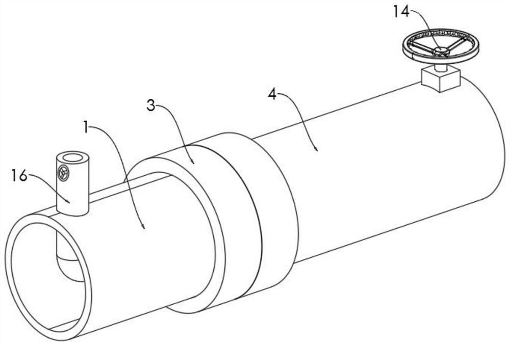
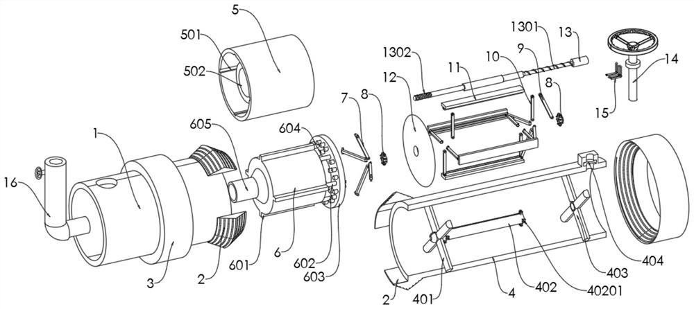
[0035] The present invention provides a municipal pipeline with a plugging device based on liquid nitrogen transportation, including a left connecting pipe 1, a right connecting pipe 4 is connected to the right end of the left connecting pipe 1, and a threaded fixing sleeve is slidably connected to the outer side wall of the connection between the left connecting pipe 1 and the right connecting pipe 4. 3. A filter cartridge 5 is welded inside the left connecting pipe 1, a backwashing cartridge 6 is slidably connected to the filter cartridge 5, a connecting arm 7 is connected to the right side wall of the backwashing cartridge 6, and a control rod 13 is rotatably connected to the middle of the right connecting pipe 4. , the left and right ends of the control rod 13 are threadedly connected with the control seat 8, the control seat 8 is connected with the pull rod 10 and the right end of the side wall support plate 11 throug...

Embodiment 2

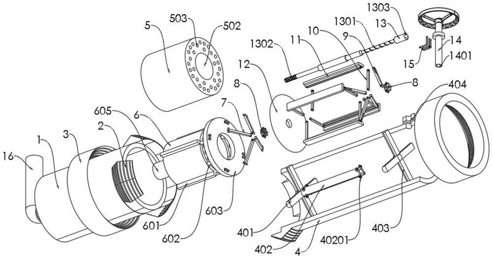
[0039] A fixed bracket 401 and a limit frame 403 are respectively arranged in the inner cavity of the left and right side of the right pipe 4. The fixed bracket 401 and the limit frame 403 are both cross-shaped, and the left and right ends of the control rod 13 are rotatably connected to the fixed bracket 401 and the limit frame. In the middle of the position frame 403, the middle of the right side wall of the fixed bracket 401 is connected with a support sleeve rod 402. The left and right outer side walls of the support sleeve rod 402 are provided with four connecting shaft seats 40201 in an annular array. A sealing ring groove 404 is opened in the block, and the rotating rod 14 is rotatably connected to the sealing ring groove 404.

[0040] Among them, five transmission holes 1303 are opened in the right side wall of the control rod 13, the left end of the L link 15 is inserted into the transmission holes 1303, and the outer side wall of the right end of the control rod 13 is...

Embodiment 3

[0043] The inner side wall of the filter cartridge 5 is provided with four long connecting chutes 501 in a circular array. The filter cartridge 5 is provided with a filter inner cylinder 502 in the middle of the inner cavity. The right end of the inner cylinder 502 is open, and a drain hole 503 is opened in the side wall of the right end of the filter cylinder 5 .

[0044] The outer side wall of the backwash cylinder 6 is provided with four connecting sliders 601 in an annular array. The six connecting cylinders 602 of the array are connected with the water blocking baffle 603, the water blocking baffle 603 is slidably connected to the outer side wall of the right side of the filter cartridge 5, and the water blocking plug 604 on the left side wall of the water blocking baffle 603 is plugged in. In the drain hole 503 on the right side wall of the filter cartridge 5 , a water outlet 605 is provided in the middle of the left side wall of the backwash cylinder 6 , and the water o...


PUM


Abstract

The invention provides a municipal pipeline provided with a plugging device and based on liquid nitrogen conveying, and relates to the field of pipeline plugging, the municipal pipeline comprises a left connecting pipe, the right end of the left connecting pipe is connected with a right connecting pipe, the outer side wall of the joint of the left connecting pipe and the right connecting pipe is slidably connected with a threaded fixing sleeve, a filter cartridge is welded in the left connecting pipe, and a backwashing cylinder is slidably connected in the filter cartridge; a connecting arm is connected to the right side wall of the backwashing cylinder, a control rod is rotationally connected to the middle of the interior of a right connecting pipe, a rotating rod drives the control rod to rotate through an L-shaped connecting rod, and the control rod drives a control seat to move leftwards through a first thread; a parallelogram structure composed of the pull rod, the side wall supporting plate and the supporting sleeve rod is driven by the main pull arm to become a rectangular structure, so that the left end of the side wall supporting plate drives the plugging face to be unfolded, the pipeline plugging operation is achieved, the plugging operation is better completed, the operation complexity is reduced, and the operation efficiency is improved. The problems that the pipeline is difficult to block and impurities are difficult to remove and filter are solved.

Description

technical field [0001] The invention relates to the technical field of pipeline plugging, in particular to a municipal pipeline equipped with a plugging device based on liquid nitrogen transportation. Background technique [0002] Municipal pipelines are an important part of urban infrastructure construction and the key to ensuring the normal operation of urban water supply and drainage systems. Pipes used for special purposes can also transport liquid nitrogen while taking into account water supply and drainage, thereby improving the diversity of pipeline use. . [0003] However, as far as the existing municipal pipelines are concerned, when the pipeline needs to be blocked, it is usually necessary to close the valve to stop the liquid supply, and then disassemble the pipeline and add plugs. The whole process requires a lot of time and manual labor. It is also inconvenient, and the impurities carried by the liquid in the pipeline are also very easy to block the pipeline. S...

Claims


Application Information

Patent Timeline
Patent Type & Authority Applications(China)
IPC IPC(8): F16L55/136F16L55/07F16L19/02B01D29/27B01D29/68
CPCF16L55/136F16L55/07F16L19/0206F16L19/0237B01D29/27B01D29/688
Inventor 谭静云
Owner 谭静云
Why Eureka
Try Eureka