Wood stick paint dyeing equipment for furniture

A technology of wooden sticks and furniture, applied in the direction of spraying devices, etc., can solve the problem of excess paint that is difficult to clean up, and achieve the effect of convenient dyeing of paint

Inactive Publication Date: 2021-01-15
吴小冬
View PDF8 Cites 6 Cited by
  • Summary
  • Abstract
  • Description
  • Claims
  • Application Information

AI Technical Summary

Problems solved by technology

[0005] In order to overcome the shortcomings of the existing method of dyeing wooden sticks for furniture, which requires manual rotation of wooden sticks, manual use of paint spraying equipment to spray paint on wooden sticks, and excessive paint is difficult to clean up, the technical problem of the present invention is to provide a method that can realize automatic transmission of wooden sticks, Wooden stick paint equipment for evenly spraying wooden sticks and conveniently cleaning excess paint on the surface of the conveyor belt

Method used


Image

  • Wood stick paint dyeing equipment for furniture
  • Wood stick paint dyeing equipment for furniture
  • Wood stick paint dyeing equipment for furniture

Examples


Embodiment 1

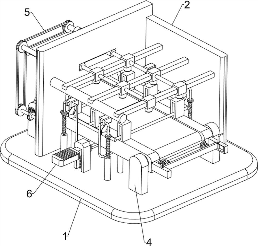
[0024] A wooden stick dyeing equipment for furniture, such as figure 1 As shown, it includes a base plate 1, a support plate 2, a servo motor 3, a transmission mechanism 4, a paint spraying mechanism 5, and a material retaining mechanism 6. There is a servo motor 3, a transmission mechanism 4 is provided on the top right side of the bottom plate 1, the parts of the transmission mechanism 4 pass through the support plate 2, and the parts of the transmission mechanism 4 are connected with the output shaft of the servo motor 3, and a paint spraying mechanism is installed on the left side of the top of the bottom plate 1 5. Parts of the painting mechanism 5 are connected to the support plate 2 , and the middle side of the top of the bottom plate 1 is provided with a stopper mechanism 6 , and the parts of the stopper mechanism 6 are connected to the parts of the transmission mechanism 4 .

[0025] When people need to dye sticks, people first place the sticks on the top of the parts...

Embodiment 2

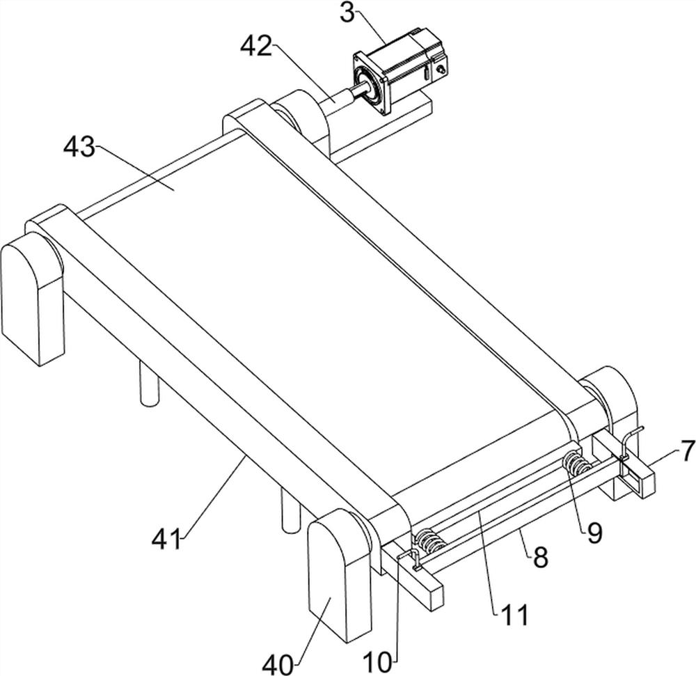
[0027] On the basis of Example 1, such as figure 2 , Figure 4 , Figure 5 with Image 6 As shown, the transmission mechanism 4 includes a mounting seat 40, a connecting plate 41, a rotating shaft 42 and a transmission belt 43. The bottom plate 1 top, front, rear, left, and right sides are all provided with mounting seats 40, between the left mounting seats 40 and the right mounting seats 40 Rotating shafts 42 are connected between them, and the left rotating shaft 42 is connected with the output shaft of the servo motor 3, and connecting plates 41 are connected in a rotating manner between the front sides of the rotating shafts 42 and the rear sides of the rotating shafts 42, and the connecting plates 41 pass through A transmission belt 43 is wound between the left side of the support plate 2 and the middle side of the rotating shaft 42 .

[0028] When people need to transport the sticks, they first place the sticks on the top right side of the transmission belt 43, and w...

Embodiment 3

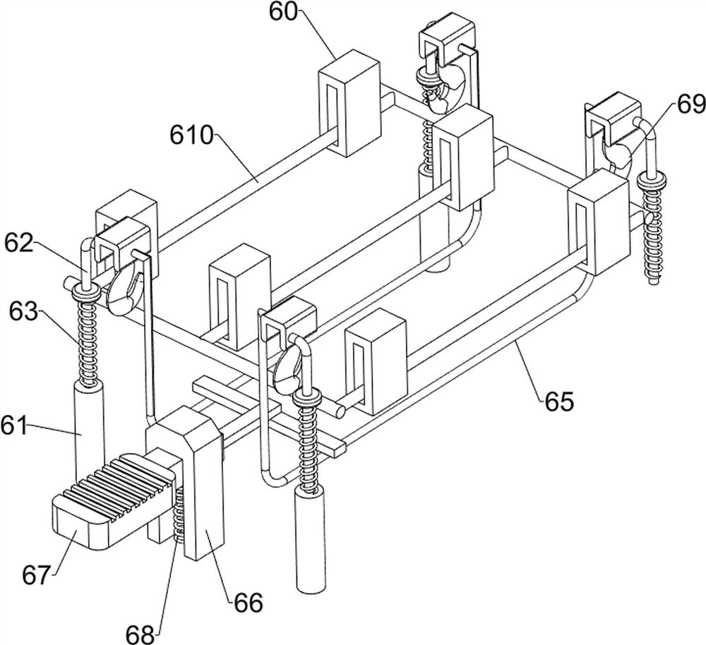
[0032] On the basis of Example 2, such as figure 2 , image 3 with Figure 7 As shown, the blocking mechanism 6 includes a sliding sleeve 60, a sliding cylinder 61, a sliding rod 62, a first spring 63, a mounting block 64, a connecting rod 65, a guide rail 66, a pedal 67, a second spring 68, a pull hook 69 and a stop frame 610, the top of the connecting plate 41 is evenly provided with sliding sleeves 60, the number of sliding sleeves 60 is 6, the middle part of the base plate 1 is provided with sliding cylinders 61 on the front, rear, left, and right sides, and the sliding cylinders 61 are all slidably connected with sliding rods 62. The first spring 63 is all connected between the upper side of the 62 and the top of the sliding tube 61, and the first spring 63 is sleeved on the slide bar 62, and the top of the slide bar 62 is provided with a mounting block 64, and between the left mounting block 64 and the right Connecting rods 65 are connected between the side mounting b...


PUM


Abstract

The invention relates to paint dyeing equipment, in particular to wood stick paint dyeing equipment for furniture. The invention provides the wood stick paint dyeing equipment for furniture capable oftransmitting wood sticks automatically, spraying paint to the wood sticks uniformly and being convenient to clean residual paint on the surface of a conveyor belt. The wood stick paint dyeing equipment for furniture comprises a bottom plate and a supporting plate, wherein the supporting plate is arranged on one side of the top of the bottom plate; a servo motor arranged on the left rear side of the top of the bottom plate; a conveying mechanism arranged on the top of the bottom plate, wherein components of the conveying mechanism penetrate through the supporting plate; a paint spraying mechanism arranged on the side, close to the servo motor, of the top of the bottom plate; and a stripping mechanism arranged on the middle side of the top of the bottom plate, wherein components of the stripping mechanism are connected to the components of the conveying mechanism. By matching the servo motor, the conveying mechanism, the paint spraying mechanism, the stripping mechanism and a scraper plate, effects of transmitting the wood sticks, uniformly spraying paint to the wood sticks and being convenient to clean residual paint on the surface of the conveyor belt can be achieved.

Description

technical field [0001] The invention relates to a paint dyeing device, in particular to a wooden stick paint dyeing device for furniture. Background technique [0002] At present, people tend to buy wooden furniture more and more when buying furniture. Many wooden furniture uses wooden sticks to assemble wooden furniture. These wooden sticks generally need to be dyed and painted before assembly, and then people use them Stained sticks for further furniture assembly. [0003] The existing method for dyeing wooden sticks is that people use clamping tools to clamp wooden sticks, and then people carry out manual spray painting on wooden sticks with hand-held painting equipment. Spraying paint by turning it is easy to cause uneven painting and affect the appearance of furniture. [0004] Therefore, it is necessary to develop a kind of furniture dyeing equipment for sticks that can realize automatic transmission of sticks, spray paint evenly on sticks and facilitate the cleaning...

Claims


Application Information

Patent Timeline
Patent Type & Authority Applications(China)
IPC IPC(8): B05B13/02B05B14/00B05B15/50
CPCB05B13/0221B05B14/00B05B15/50
Inventor 吴小冬
Owner 吴小冬
Why Eureka
Try Eureka