Self-locking device for lifting structure of mining machinery

A lifting structure and self-locking device technology, which is applied in the direction of lifting devices, transmission devices, mechanical equipment, etc., can solve the problems of lengthening, affecting the service life of servo motors, and damage to servo motors

Active Publication Date: 2021-01-15
上海兴羌矿业有限公司
View PDF16 Cites 1 Cited by
  • Summary
  • Abstract
  • Description
  • Claims
  • Application Information

AI Technical Summary

Problems solved by technology

[0002] The lifting structure is one of the commonly used mechanical structures in mining machinery. At present, the screw rod placed in the cylinder is driven by a servo motor to rotate, so that the ball nut pair on the screw rod converts the rotational motion of the screw rod into a linear motion and drives the inner cylinder in the The cylinder moves inside, so that the length formed by the inner cylinder and the cylinder body becomes longer or shorter, achieving self-locking while lifting, but the weight of the inner cylinder and the weight of the components connected to the inner cylinder directly act on the output of the servo motor end, it is easy to cause damage to the servo motor and affect the service life of the servo motor

Method used


Image

  • Self-locking device for lifting structure of mining machinery
  • Self-locking device for lifting structure of mining machinery
  • Self-locking device for lifting structure of mining machinery

Examples


specific Embodiment approach

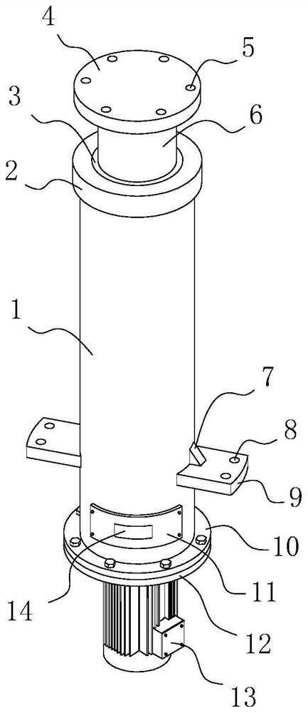
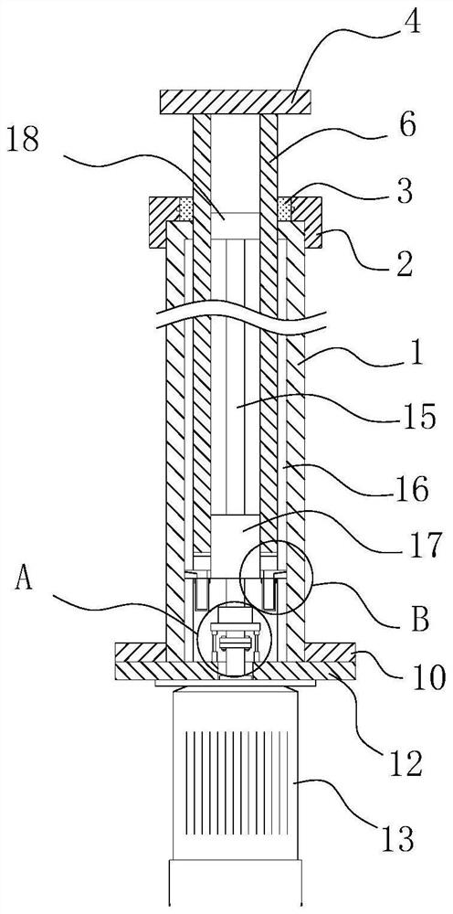
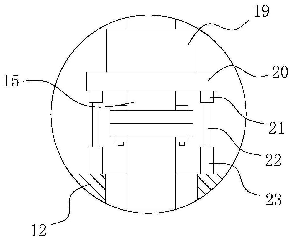
[0040]Specific embodiments: the bolts of the fixing connecting plate 9 are installed at the required position through the insertion hole 8 to complete the fixing of the position of the connecting plate 9, that is, the position of the cylinder 1 is limited, and the connecting plate 4 is used to connect the inner cylinder 6 with The components that need to be driven are connected, and the servo motor 13 is controlled by PLC to rotate forward or reverse, and then the ball nut pair 17 converts the rotary motion of the screw rod 15 into linear motion and drives the inner cylinder 6 to move in the cylinder 1, thereby achieving lifting At the same time, the ball nut pair 17 drives the sliding block 24 to slide along the sliding groove 16, and the sliding block 24 scrapes the dust attached to the inner surface of the sliding groove 16 into the groove 25 during the sliding process, and then falls into the groove 25 The dust inside slides along the inclined surface of the inner bottom of the ...


PUM


Abstract

The invention relates to the technical field of mining machinery, in particular to a self-locking device for a lifting structure of mining machinery. The self-locking device comprises a cylinder body,a blind plate, an inner cylinder, a servo motor, a screw rod, a ball nut pair, a slide block, a sliding chute and a pressure transfer assembly. The ball nut pair converts a rotary motion of the leadscrew into a linear motion and drives the inner cylinder to move in the cylinder body when the servo motor drives the lead screw to rotate, so that a lifting purpose is achieved. By arranging the pressure transfer assembly on the outer surface of the lower end of the lead screw in a sleeving manner, the weight of the inner cylinder and the weight of a part connected to the inner cylinder are transferred to the blind plate through the pressure transfer assembly so as to prevent the pressure from directly acting on the servo motor to achieve the pressure transfer purpose, so that a condition that the servo motor that is pressed is damaged is avoided.

Description

Technical field[0001]The invention is a self-locking device for the lifting structure of mining machinery, belonging to the technical field of mining machinery.Background technique[0002]The lifting structure is one of the commonly used mechanical structures in mining machinery. At present, the servo motor is used to drive the screw rod placed in the cylinder to rotate, so that the ball nut pair on the screw rod converts the rotation movement of the screw rod into linear motion and drives the inner cylinder The cylinder body moves, so that the length formed by the inner cylinder and the cylinder body becomes longer or shorter, achieving self-locking while achieving lifting, but the weight of the inner cylinder and the weight of the parts connected to the inner cylinder directly act on the output of the servo motor It is easy to damage the servo motor and affect the service life of the servo motor.Summary of the invention[0003]In view of the deficiencies in the prior art, the purpose ...

Claims


Application Information

Patent Timeline
Patent Type & Authority Applications(China)
IPC IPC(8): B66F3/44B66F3/10F16H25/22
CPCB66F3/44B66F3/10F16H25/2204F16H2025/204F16H2025/2075
Inventor 竺秋君
Owner 上海兴羌矿业有限公司
Why Eureka
Try Eureka