Multi-stage elastic cabin vibration isolating device realizing vibration damping based on pneumatic tire

A vibration isolation, pneumatic tire technology, applied in the direction of engine sealing, spring/shock absorber, vibration suppression adjustment, etc., can solve the problems of difficult to achieve effective sealing of cabin pipelines, general vibration isolation effect, poor sealing performance, etc. Good vibration isolation effect, reasonable overall design, and the effect of reducing radial stiffness

Inactive Publication Date: 2019-04-19
NAVAL UNIV OF ENG PLA
View PDF6 Cites 3 Cited by
  • Summary
  • Abstract
  • Description
  • Claims
  • Application Information

AI Technical Summary

Problems solved by technology

However, the traditional elastic penetrating vibration isolation structure mostly uses a structure filled with solid rubber and damping material between the pipeline and the inner hole of the penetrating part. The stiffness of this vibration isolation structure is completely determined by the size and elastic modulus of the rubber material. , the stiffness may be further reduced, the vibration isolation effect is general, it is difficult to effectively isolate the vibration from being transmitted to the outside; and the sealing performance is poor, it is difficult to achieve effective sealing between the cabin pipeline and the bulkhead, and between the bulkhead and the bulkhead

Method used


Image

  • Multi-stage elastic cabin vibration isolating device realizing vibration damping based on pneumatic tire

Examples


Embodiment Construction

[0020] In order to better understand the present invention, the present invention will be further described below in conjunction with the accompanying drawings and specific embodiments.

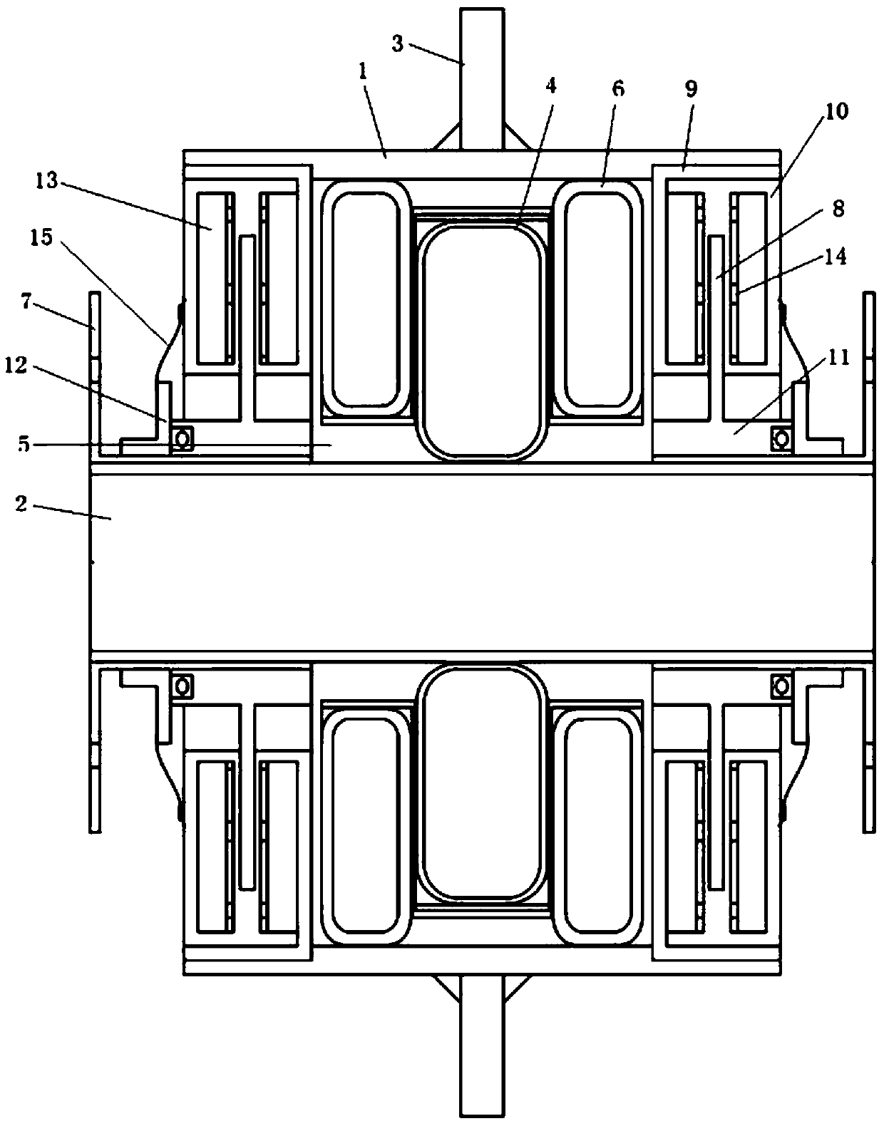
[0021] Such as figure 1 The shown multi-stage elastic cabin vibration isolation device based on pneumatic tire vibration reduction includes a casing 1, two end connectors, and a vibration isolation assembly and two seals that are all located inside the casing 1. The casing 1 The outer wall is fixedly connected to the cabin bulkhead 3 (can be welded), the sealing assembly is symmetrically arranged around the vibration isolation assembly, the sealing assembly and the vibration isolation assembly are coaxially sleeved on the pipeline 2, and the end faces of the two are compressed; Two end connectors are respectively arranged at two ends of the housing 1 and connected with the sealing assembly.

[0022] Preferably, the vibration isolation assembly includes a primary vibration isolation group and...


PUM


Abstract

The invention discloses a multi-stage elastic cabin vibration isolating device realizing vibration damping based on a pneumatic tire. The multi-stage elastic cabin vibration isolating device comprisesa housing, two end part connecting parts, a vibration isolating component and two sealing parts, wherein the vibration isolating component and the two sealing parts all are arranged inside the housing; the outer wall of the housing is fixedly connected with the wall of a cabin; the sealing parts are symmetrically arranged by taking a vibration isolating component as the center; the sealing partsand the vibration isolating component are coaxially arranged on a pipeline in a sleeving manner, and the end faces of the sealing parts and the vibration isolating component are pressed closely; the two end part connecting parts are correspondingly arranged at the two ends of the housing and are connected with the sealing parts; the vibration isolating component comprises a first-stage vibration isolating group; the first-stage vibration isolating group comprises a plurality of first-stage pneumatic tires which are nested in the radial direction; and the outer circumferential surface of each first-stage pneumatic tire is provided with a plurality of circumferential saw-toothed slots. The multi-stage elastic cabin vibration isolating device disclosed by the invention has the beneficial effects that a plurality of layers of pneumatic tires are overlapped together to form a pneumatic tire structure having a cavity; the structure is deformed after being extruded; the air in the cavity alsohas certain rigidity; and thus multi-stage vibration isolation is realized in the radial direction.

Description

technical field [0001] The invention relates to the technical field of ship vibration reduction, in particular to a multi-stage elastic cabin penetrating vibration isolation device based on pneumatic tire vibration reduction. Background technique [0002] Various mechanical equipment and pipelines are one of the main noise sources of ships. If the vibration is not effectively isolated, the vibration will be transmitted to the bulkhead to cause sound radiation, which will affect its acoustic stealth performance. The elastic penetrating vibration isolation structure is an installation part of the hull bulkhead, which is mainly used for the part where the pipeline penetrates the bulkhead. The elastic penetrating vibration isolation structure is used as a pipeline connection and a hull bulkhead reinforcement, and it also has vibration isolation capabilities compared to other bulkhead installations. However, the traditional elastic penetrating vibration isolation structure mostl...

Claims


Application Information

Patent Timeline
Patent Type & Authority Applications(China)
IPC IPC(8): F16F15/023F16J15/52F16J15/46
CPCF16F15/023F16J15/46F16J15/52
Inventor 杨庆超杜奎刘树勇李爽
Owner NAVAL UNIV OF ENG PLA
Why Eureka
Try Eureka