
Optical cable cutting precise positioning device

A precise positioning, optical cable technology, applied in the measurement device, the use of fluid devices, the coupling of optical waveguides, etc., can solve the problems of inaccurate cutting length, unfavorable use, uneven incision, etc., to improve cutting efficiency, reduce manual errors, Enhanced gripping force effect

Active Publication Date: 2021-07-30
SUZHOU BECKE ELECTRIC TECH CO LTD
View PDF7 Cites 0 Cited by
  • Summary
  • Abstract
  • Description
  • Claims
  • Application Information

AI Technical Summary

Problems solved by technology

Most of the optical cable cutting devices currently on the market use clamps for cutting. The clamps will not only move the communication optical cable during use, but also cause the phenomenon of bending the communication optical cable when it is cut, resulting in the inefficiency of cutting the communication optical cable. low, not conducive to the use of people
[0004] Moreover, the existing optical cable cutting device does not have the function of measuring the laying length of the optical cable, and the inaccurate cutting length will easily cause waste, and when the optical cable is cut, the cutting efficiency is low, and the cut is not neat

Method used


Image

  • Optical cable cutting precise positioning device
  • Optical cable cutting precise positioning device
  • Optical cable cutting precise positioning device

Examples


Embodiment Construction

[0032] The following will clearly and completely describe the technical solutions in the embodiments of the present invention with reference to the accompanying drawings in the embodiments of the present invention. Obviously, the described embodiments are only some, not all, embodiments of the present invention. Based on the embodiments of the present invention, all other embodiments obtained by persons of ordinary skill in the art without making creative efforts belong to the protection scope of the present invention.

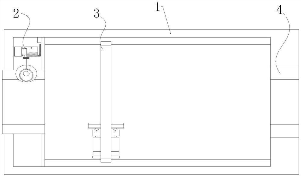
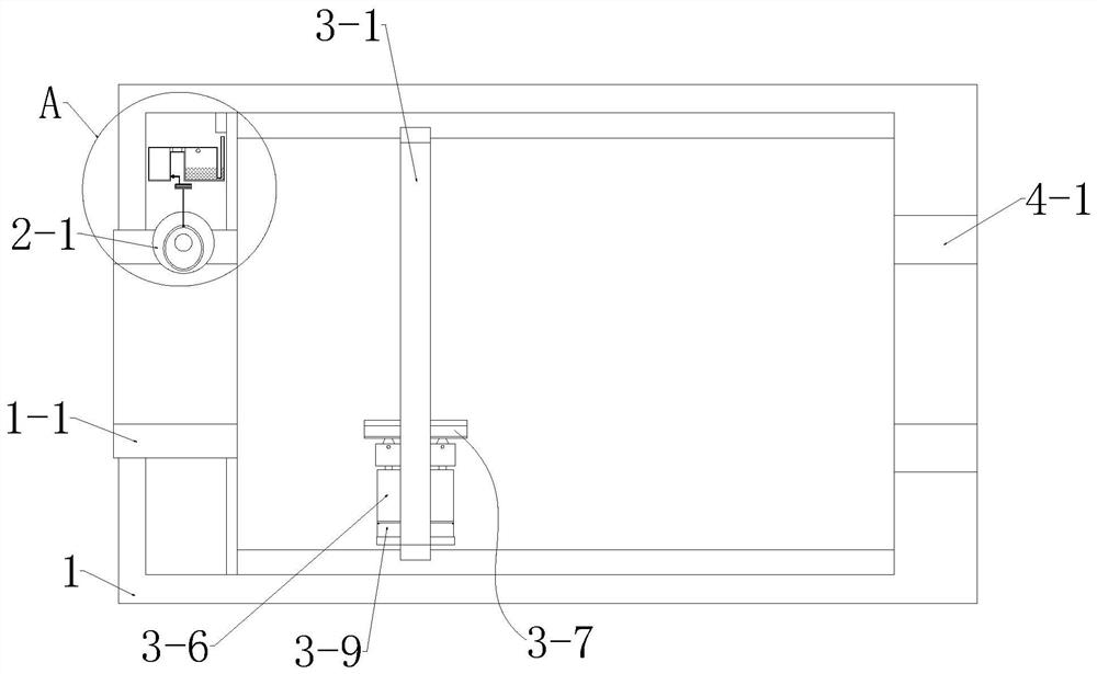
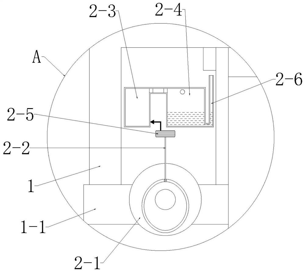
[0033] see Figure 1-8 , the present invention provides a technical solution: a precise positioning device for optical cable cutting, the precise positioning device includes a housing 1, a distance measuring mechanism 2, a cutting mechanism 3, and an auxiliary mechanism 4, and the distance measuring mechanism 2 and the cutting mechanism are installed in the housing 1 from left to right 3. The auxiliary mechanism 4, the distance measuring mechanism 2 measures t...


PUM


Abstract

The invention discloses a precise positioning device for optical cable cutting. The precise positioning device includes a casing, a distance measuring mechanism, a cutting mechanism, and an auxiliary mechanism. The distance measuring mechanism measures the length of the optical cable through air pressure, the cutting mechanism cuts the optical cable circularly, and the auxiliary mechanism assists the cutting mechanism to cut the optical cable. The cutting mechanism is equipped with a clamping and fixing component. After the clamping and fixing component clamps and fixes the optical cable, the cutting component in the cutting mechanism performs circular cutting on the optical cable to speed up the cutting efficiency of the optical cable. The present invention has the advantages of precise positioning and fast cutting of the optical cable Effect.

Description

technical field [0001] The invention relates to the technical field of optical cable positioning and cutting, in particular to a precise positioning device for optical cable cutting. Background technique [0002] With the development of society, the application of optical cables is more extensive, and it is often necessary to bury optical cables outdoors, beside roads, etc. to complete optical cable channels. Optical cables are manufactured to meet optical, mechanical or environmental performance specifications. They are communication optical cable assemblies that use one or more optical fibers wrapped in a sheath as the transmission medium and can be used individually or in groups. The optical cable is composed of a cable core and an outer sheath composed of several optical fibers (generally from several cores to several thousand cores). [0003] Compared with the traditional symmetrical copper circuit and coaxial copper circuit, optical fiber has the following advantages:...

Claims


Application Information

Patent Timeline
Patent Type & Authority Patents(China)
IPC IPC(8): G02B6/25G01B13/02
CPCG01B13/02G02B6/25
Inventor 祁星星
Owner SUZHOU BECKE ELECTRIC TECH CO LTD
Learn More