
Display control system and display control method

A technology of display control and control part, which is applied to program control devices, instruments, electrical and digital data processing, etc., can solve problems such as trouble for users, and achieve the effect of suppressing wrong selection.

Pending Publication Date: 2021-01-15
ALPINE ELECTRONICS INC
View PDF1 Cites 0 Cited by
  • Summary
  • Abstract
  • Description
  • Claims
  • Application Information

AI Technical Summary

Problems solved by technology

[0008] However, in the technique of Patent Document 1, there is a problem that even when the user desires to select an icon whose touch sensitivity is suppressed, the user needs to touch the icon strongly and for a long time, which may become troublesome for the user. reason

Method used


Image

  • Display control system and display control method
  • Display control system and display control method
  • Display control system and display control method

Examples


no. 1 Embodiment approach >

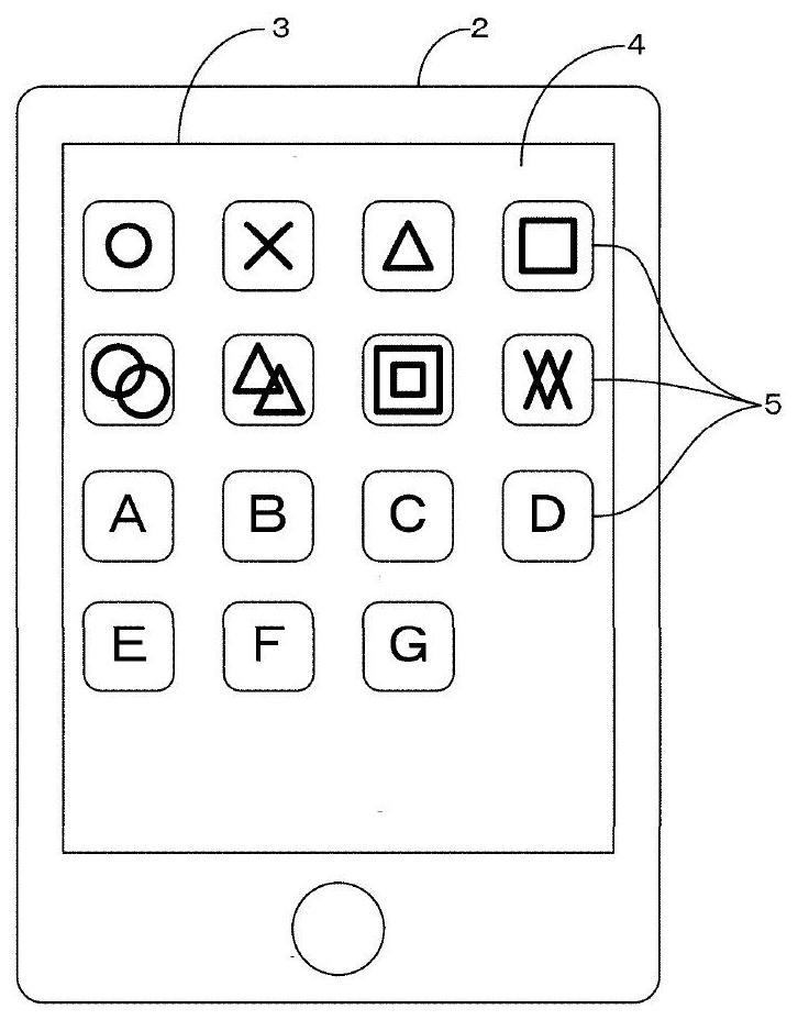
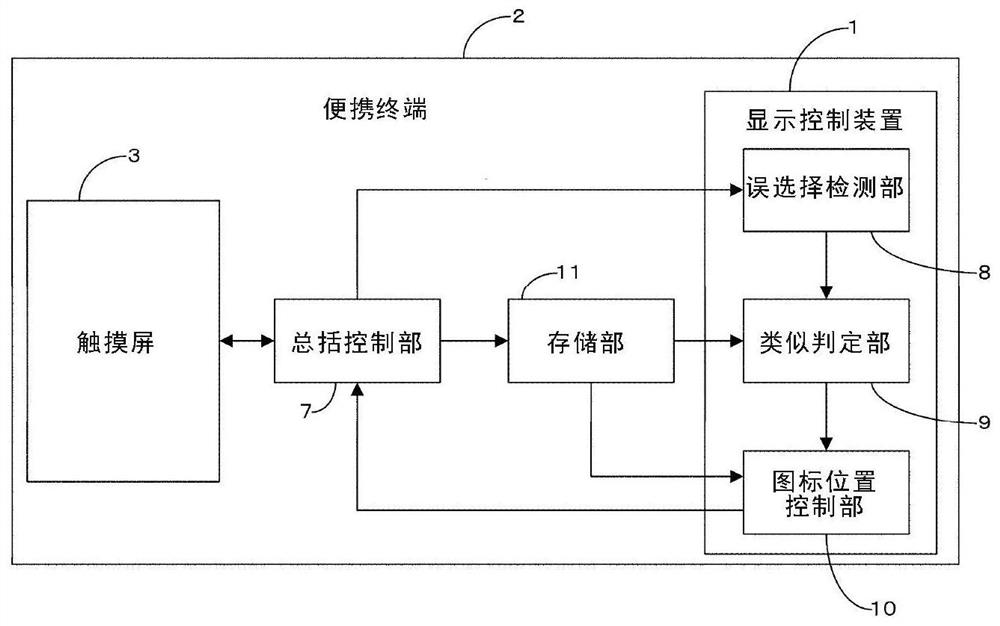
[0033] Hereinafter, a first embodiment of the present invention will be described based on the drawings. figure 1 is configured to include the display control device 1 of this embodiment ( figure 2 ) of the front view of the portable terminal 2. In this embodiment, the display control device 1 functions as a "display control system" within the scope of the patent claims. The portable terminal 2 of the present embodiment includes a plate-shaped housing and a touch panel 3 provided in a wide area on the front surface of the housing. So-called smartphones and tablet-type computers correspond to the portable terminal 2 . The touch panel 3 includes a display panel such as a liquid crystal display or an organic EL panel, and a touch sensor that is arranged to overlap the display panel and detects a touch operation by a user.

[0034] In the portable terminal 2 of the present embodiment, a lock screen is provided by the function of the OS, and after unlocking by password input, b...

no. 2 Embodiment approach >

[0111] Next, a second embodiment will be described. In the following description of the second embodiment, the same elements as those of the first embodiment are given the same symbols as those of the first embodiment, and detailed description thereof will be omitted. Figure 9 It is a block diagram showing a functional configuration example of a mobile terminal 2A including the display control device 1A and an on-vehicle device 20 capable of communicating with the mobile terminal 2A according to the second embodiment. In this embodiment, the display control device 1A functions as a "display control system" within the scope of the patent claims. The vehicle-mounted device 20 is a device mounted on a vehicle, and includes a vehicle-mounted touch panel 21 for visual recognition by the driver and other passengers. In addition, the portable terminal 2A of this embodiment is a device which a vehicle occupant brings into the vehicle.

[0112] Such as Figure 9 As shown, the porta...

no. 3 Embodiment approach >

[0167] Next, a third embodiment will be described. In the following description of the third embodiment, the same elements as those of the first embodiment are given the same symbols as those of the first embodiment, and detailed description thereof will be omitted.


PUM


Abstract

[Problem] To provide a display control system and a display control method that suppress erroneous selection of icons while maintaining a state in which each icon can be selected by a touch operationin a normal form. A display control device (1), which functions as a display control system, is provided with a misselection detection unit (8) which detects that a user has selected another icon by mistaking another icon with a certain icon; a similarity determination unit (9) which determines whether or not the two wrongly selected icons are similar; and an icon position control unit (10) whichchanges the positional relationship in the icon display screen for two icons that are erroneously selected and similar to each other, and that, when there is erroneous selection by the user, can change the positional relationship of each icon at the current time to a relationship in which erroneous selection by the user becomes less.

Description

technical field [0001] The present invention relates to a display control system and a display control method, and in particular to a technique suitable for use in a display control system for controlling the display of a display device capable of displaying an icon display screen on which a plurality of icons selectable by touch operations are arranged. Background technique [0002] In recent years, terminals that display a screen on which a plurality of icons selectable by a touch operation are displayed on a touch panel are widely used. For example, among terminals such as so-called smartphones and tablet computers, terminals in which icons corresponding to applications installed in the terminal are arranged and displayed on the home screen after unlocking are widely used. To select an icon, the terminal corresponding to the application program starts. [0003] In such a terminal displaying a plurality of icons on the touch panel, the user may mistakenly select an icon. ...

Claims


Application Information

Patent Timeline
IPC IPC(8): G06F9/451G06F3/0481G06F3/0488
CPCG06F9/451G06F3/04817G06F3/0488
Inventor 牟雯雯
Owner ALPINE ELECTRONICS INC
Learn More