Dual hot standby switching method and device

A dual-machine hot standby and switching request technology, applied in the field of communication, can solve problems such as high development and maintenance costs, large system modifications, and affecting device forwarding performance, and achieve low development and maintenance costs and small system modifications.

Pending Publication Date: 2021-01-15
北京中科网威信息技术有限公司
View PDF0 Cites 0 Cited by
  • Summary
  • Abstract
  • Description
  • Claims
  • Application Information

AI Technical Summary

Problems solved by technology

[0004] The existing dual-system hot backup solution can only complete the switch by judging whether the service port is open (up) / down. Taking a firewall as an example, when the firewall dual-system hot backup However, when the power is not turned off, and the service port is still in the state of suspended animation), the state of the service port cannot be effectively monitored and the switch to the backup link can be completed in time
[0005] In addition, the current method needs to support the BFD (Bidirectional Forwarding Detection) protocol and the linkage of the system's dual-machine hot backup function, which requires a large amount of system modification and high development and maintenance costs.
At the same time, the BFD function of the uplink and downlink devices needs to be enabled when the firewall is deployed with dual-system hot backup. Even if the uplink and downlink devices support this function, after the BFD function is enabled, certain business expenses will be caused to the uplink and downlink devices, which will affect the forwarding performance of the devices.

Method used


Image

  • Dual hot standby switching method and device
  • Dual hot standby switching method and device
  • Dual hot standby switching method and device

Examples


Embodiment Construction

[0022] In order to make the purpose, technical solutions and advantages of the embodiments of the present invention clearer, the technical solutions in the embodiments of the present invention will be clearly and completely described below in conjunction with the drawings in the embodiments of the present invention. Obviously, the described embodiments It is a part of embodiments of the present invention, but not all embodiments. Based on the embodiments of the present invention, all other embodiments obtained by persons of ordinary skill in the art without creative efforts fall within the protection scope of the present invention.

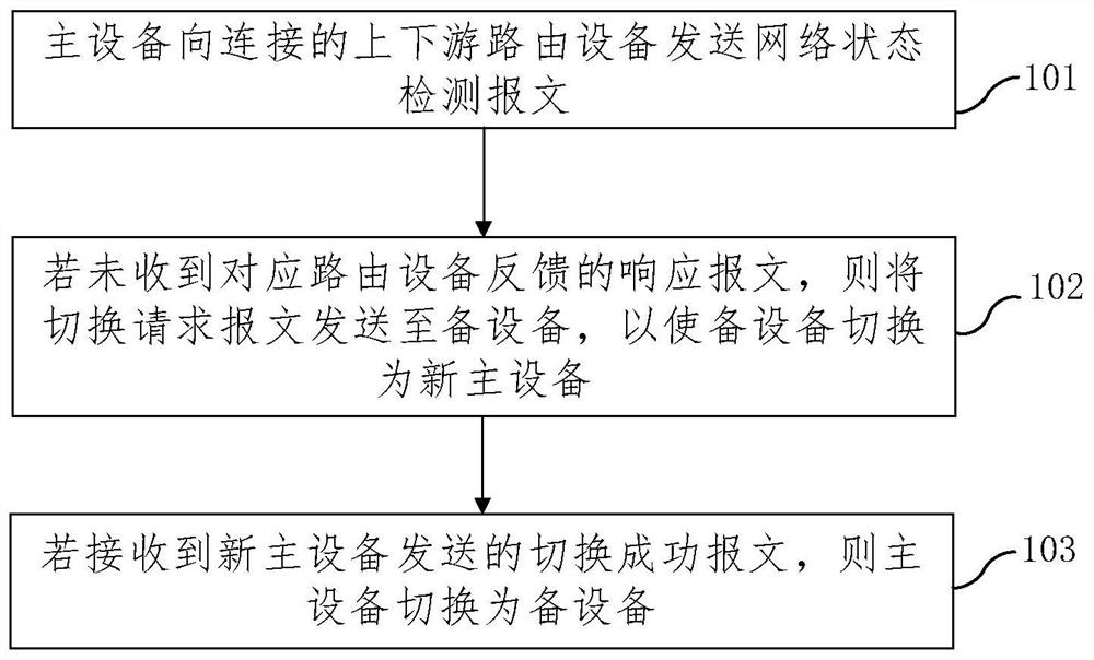
[0023] Combine below Figure 1-Figure 3 The dual-system hot standby switching method and device of the embodiments of the present invention are described. figure 1 It is a schematic flow chart of a dual-system hot standby switching method provided by an embodiment of the present invention, as shown in figure 1 As shown, the embodiment of the pre...


PUM


Abstract

The embodiment of the invention provides a dual hot standby switching method and device. The method comprises the following steps: a main device sends a network state detection message to connected uplink and downlink routing reachable equipment; if the response message fed back by the corresponding route reachable device is not received, the detection result or the switching request are sent to the standby device, so that the standby device is switched to a new main device; and if a switching success message sent by the new main device is received, the main device is switched to the standby device. The method is implemented by sending a network state detection message and receiving a response message through main equipment, and switching between the main device and the standby device canbe achieved as long as response messages of upper and lower networking gateways or server equipment can be received under the condition that the existing topological environment and configuration of aclient are not modified. The situation that the main and standby links cannot be switched due to false death of the uplink and downlink equipment is avoided. Meanwhile, only a hot backup device needsto be configured, the system modification amount is small, and the development and maintenance cost is low.

Description

technical field [0001] The invention relates to the technical field of communications, in particular to a method and device for dual-system hot standby switching. Background technique [0002] The dual-machine hot standby system is the smallest unit of the cluster, which is to install the central server as two servers for mutual backup, and only one server is running at the same time. When one of the running servers fails to start due to failures such as business port shutdown (down), abnormal server restart, or power failure, the other backup server will automatically start and run quickly (usually within a few minutes), thus ensuring The normal operation of the entire network system. The working mechanism of dual-system hot backup actually provides a failure automatic recovery capability for the central server of the entire network system. [0003] In the dual-machine hot standby system, the device completes the master-standby switchover by setting the measurement value ...

Claims


Application Information

Patent Timeline
Patent Type & Authority Applications(China)
IPC IPC(8): G06F11/20
CPCG06F11/2028G06F11/2038
Inventor 李鼎权
Owner 北京中科网威信息技术有限公司
Why Eureka
Try Eureka