Multi-chip debugging method and multi-chip debugging device
A multi-chip, chip technology, applied in the field of communication, can solve the problems of slow debugging, complicated wiring, inconvenient maintenance, etc., to achieve the effect of simple wiring and easy maintenance
- Summary
- Abstract
- Description
- Claims
- Application Information
AI Technical Summary
Problems solved by technology
Method used
Image

Examples
Embodiment Construction
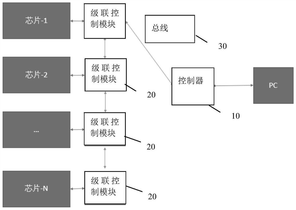
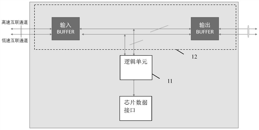
[0015] Embodiments of the present disclosure will be described in detail below in conjunction with the accompanying drawings.
[0016] Embodiments of the present disclosure are described below through specific examples, and those skilled in the art can easily understand other advantages and effects of the present disclosure from the contents disclosed in this specification. Apparently, the described embodiments are only some of the embodiments of the present disclosure, not all of them. The present disclosure can also be implemented or applied through different specific implementation modes, and various modifications or changes can be made to the details in this specification based on different viewpoints and applications without departing from the spirit of the present disclosure. It should be noted that, in the case of no conflict, the following embodiments and features in the embodiments can be combined with each other. Based on the embodiments in the present disclosure, a...
PUM
 Abstract
Description
Claims
Application Information
PatSnap Eureka turns technology decisions into work you can execute. Powered by our Innovation Knowledge Graph, it runs expert workflows across engineering, life sciences, materials and intellectual property. Get your review-ready output in minutes.


