Deicing device for power transmission line

A transmission line and electric power technology, which is applied in the direction of electromechanical devices, cable installation, electric components, etc., can solve the problems of high cost and difficulty of deicing, tower collapse, power interruption, etc., and achieve better deicing effect and convenient movement Effect

Pending Publication Date: 2021-01-15
湖北启进电力科技有限公司
View PDF4 Cites 3 Cited by
  • Summary
  • Abstract
  • Description
  • Claims
  • Application Information

AI Technical Summary

Problems solved by technology

The overloaded gravity brought by severe line icing will break the transmission line, and even cause the tower to collapse, causing large-scale power interruptions and causing huge economic losses. In a word, icing accidents seriously threaten the safety of my country's power system run
[0003] At present, the risk elimination methods adopted are mainly to melt ice by heating on the power transmission line. Transmission lines), high-frequency excitation ice melt

Method used


Image

  • Deicing device for power transmission line
  • Deicing device for power transmission line
  • Deicing device for power transmission line

Examples


Example Embodiment

[0026] Example 1

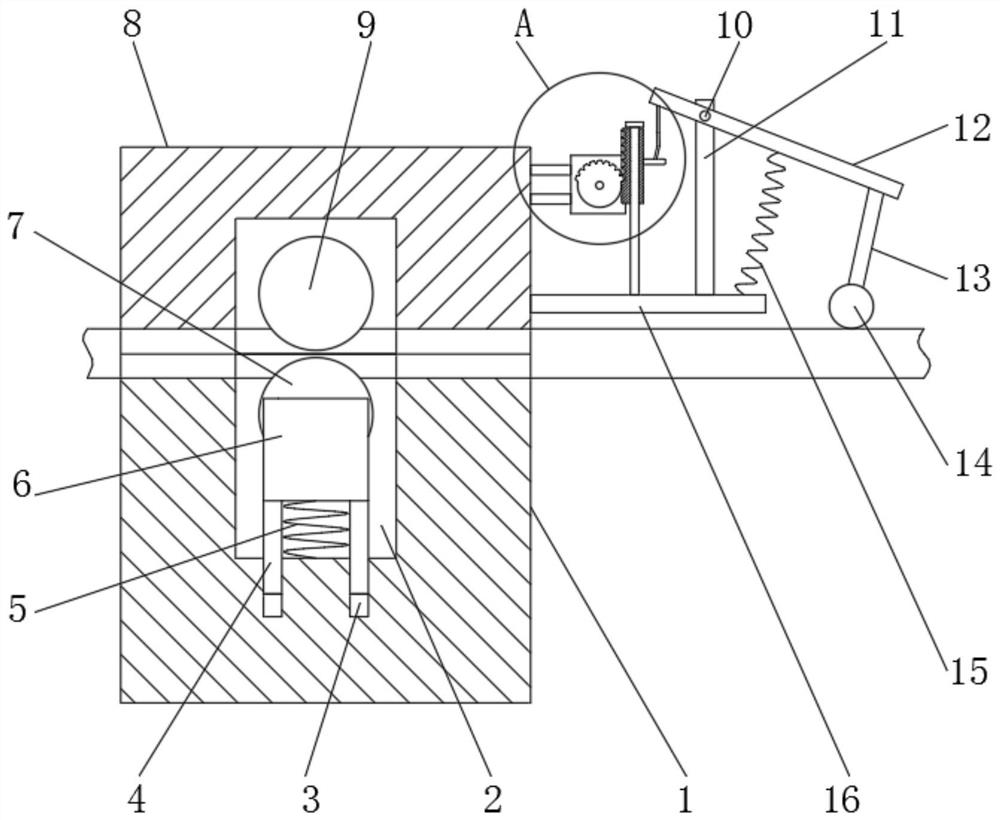
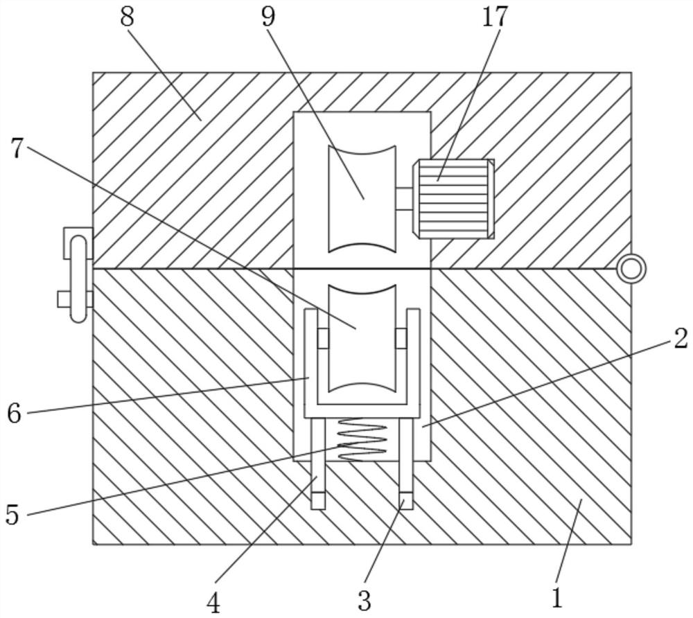
[0027] refer to Figure 1-4 , a deicing device for power transmission lines, comprising a lower fixing base 1 and an upper fixing base 8, the lower fixing base 1 and the upper fixing base 8 are connected by hinge rotation, and the buckles on the upper fixing base 8 and The clips on the lower fixing base 1 are connected with each other, the top outer wall of the lower fixing base 1 is provided with an installation groove 2, and the bottom inner wall of the installation groove 2 is opened with a limit groove 3, and the inner wall of the limit groove 3 is slidably connected with a sliding rod 4 , and the top outer wall of the sliding rod 4 is fixedly connected with the ear seat 6, the inner wall of the ear seat 6 is connected with the roller 7 through the bearing rotation, the bottom inner wall of the installation groove 2 is fixedly provided with a first spring 5, and one end of the first spring 5 and The bottom outer wall of the ear seat 6 is fixedly connect...

Example Embodiment

[0032] Example 2

[0033] refer to Figure 5 , a deicing device for power transmission lines. Compared with Embodiment 1, this embodiment also includes a universal ball 26 provided on one side outer wall of the lower fixing base 1, and the outer wall of the universal ball 26 passes through the third The spring 27 is connected with a vibrating block 28, and one outer wall of the vibrating block 28 is provided with ice-crushing teeth 29 distributed at equal distances, which can break the icicles and facilitate the movement of the device.

[0034] A cavity is provided inside the vibration block 28 , and a vibration motor 30 is provided inside the cavity.

[0035] Working principle: During use, since the vibration block 28 and the universal ball 26 are connected by the third spring 27, when the vibration motor 30 is driven to work, the vibration block 28 can be driven to vibrate on the universal ball 26, and the vibration block 28 can be driven to vibrate on the universal ball 26...


PUM


Abstract

The invention discloses a deicing device for a power transmission line. The device comprises a lower fixed seat and an upper fixed seat, the lower fixed seat and the upper fixed seat are rotatingly connected through a hinge, a buckle on the upper fixed seat is buckled with a clamping seat on the lower fixed seat, the outer wall of the top of the lower fixed seat is provided with a mounting groove,a limiting groove is formed in the inner wall of the bottom of the mounting groove, a sliding rod is slidably connected with the inner wall of the limiting groove, a lug seat is fixedly connected with the outer wall of the top of the sliding rod, a roller is rotatably connected with the inner wall of the lug seat through a bearing, a first spring is fixedly arranged on the inner wall of the bottom of the mounting groove, one end of the first spring is fixedly connected with the outer wall of the bottom of the lug seat, and a fixing groove is formed in the outer wall of the bottom of the upperfixed seat. According to the invention, the driving wheel and the roller can clamp power transmission lines with different thicknesses, the use is more flexible, automatic deicing is realized, manualbeating is not needed, and the deicing effect is better.

Description

technical field [0001] The invention relates to the technical field of power transmission line maintenance, in particular to a deicing device for power transmission lines. Background technique [0002] Transmission lines play an important role in the transmission of electricity. Ensuring the safe and reliable operation of transmission lines is of great significance to ensuring the stable and healthy development of the national economy. Occurrence of icing on the surface. The overloaded gravity brought by severe line icing will break the transmission line, and even cause the tower to collapse, causing large-scale power interruptions and causing huge economic losses. In a word, icing accidents seriously threaten the safety of my country's power system run. [0003] At present, the risk elimination methods adopted are mainly to melt ice by heating on the power transmission line. Transmission lines), high-frequency excitation ice melting (using the skin effect of high-frequenc...

Claims


Application Information

Patent Timeline
IPC IPC(8): H02G7/16H02K7/116H02K7/06H02K7/14
CPCH02G7/16H02K7/116H02K7/06H02K7/14
Inventor 王递进
Owner 湖北启进电力科技有限公司
Why Eureka
Try Eureka