
Drilling device for processing doors and windows

A drilling device, door and window technology, applied in the direction of positioning device, boring/drilling, metal processing equipment, etc., can solve the problem of affecting drilling accuracy, unfavorable multi-angle drilling, clamping support mechanism and drilling mechanism can not Angle adjustment and other issues to achieve the effect of precise drilling and strong practicability

Inactive Publication Date: 2021-01-19
张锋凯
View PDF0 Cites 3 Cited by
  • Summary
  • Abstract
  • Description
  • Claims
  • Application Information

AI Technical Summary

Problems solved by technology

Doors and windows need to be drilled during the processing process. The clamping support mechanism and drilling mechanism of the existing drilling device for door and window processing generally cannot adjust the angle, which is not conducive to multi-angle drilling, thereby affecting the drilling accuracy.

Method used


Image

  • Drilling device for processing doors and windows
  • Drilling device for processing doors and windows
  • Drilling device for processing doors and windows

Examples


Embodiment 1

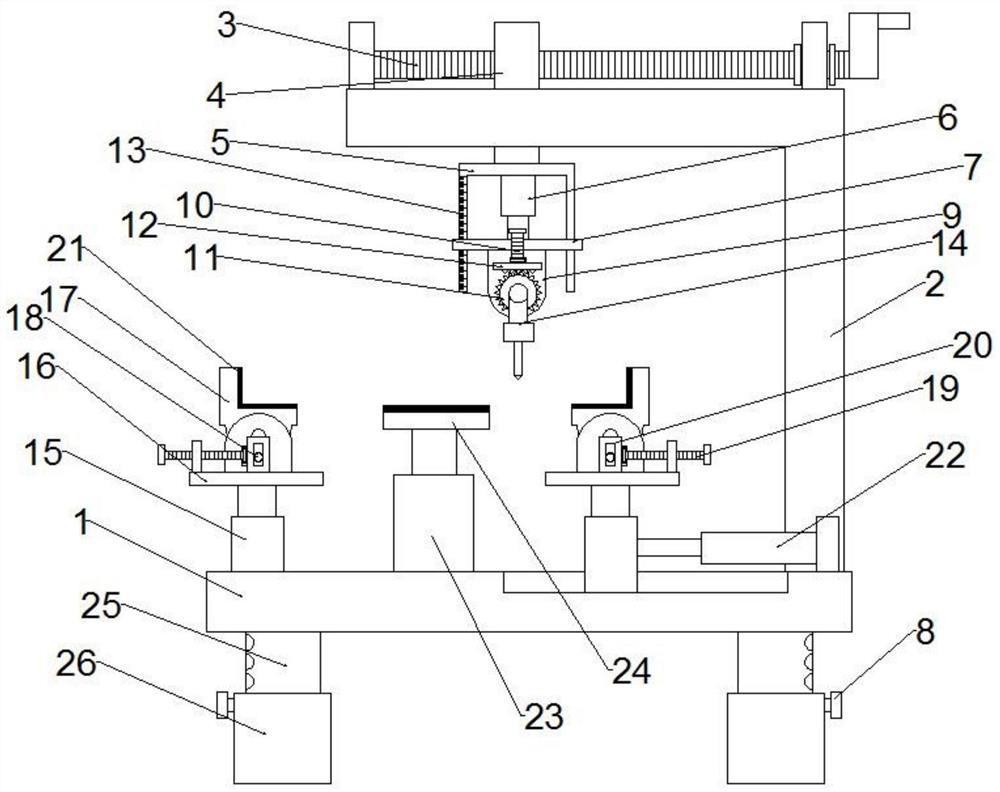
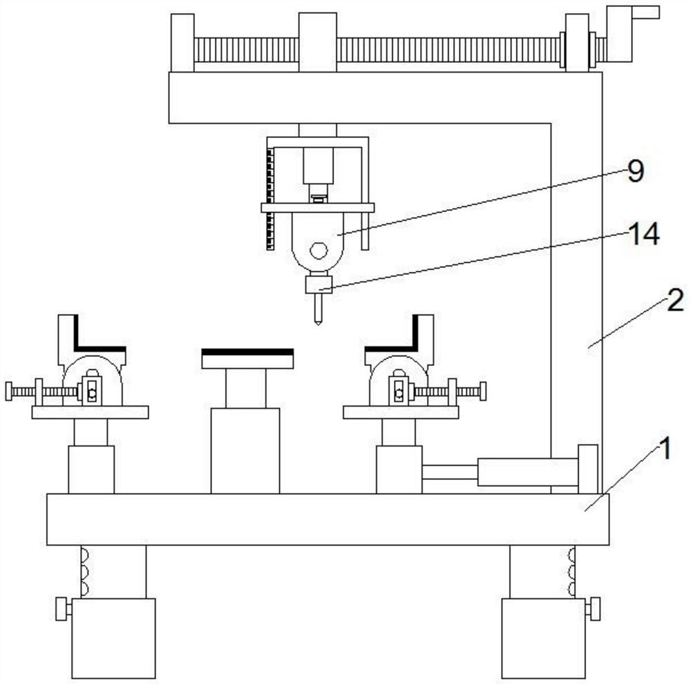
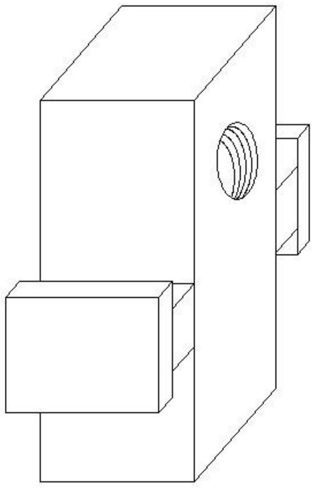
[0019] see Figure 1-3 , a drilling device for door and window processing, including a base plate 1, a clamping support mechanism and a drilling mechanism, the clamping support mechanism includes a clamping seat 17, and the left and right sides of the upper end of the base plate 1 are respectively provided with a cylinder one 15 The cylinder one 15 on the left side is fixedly arranged on the upper end of the base plate 1, the cylinder one 15 on the right side is slidably arranged on the upper end of the base plate 1, and the upper right end of the base plate 1 is laterally fixed with the cylinder two 22, the The left end of the piston rod at the output end of the cylinder two 22 is fixedly connected to the right side of the cylinder one 15 on the right side, the upper end of the cylinder one 15 is respectively fixed with a support plate one 16, and the bottom side of the clamping seat 17 is fixed respectively A rotating shaft is interspersed, and the clamping seat 17 is arrang...

Embodiment 2

[0027] see Figure 1-3 , this embodiment is a further optimization carried out on the basis of Embodiment 1, specifically: the left and right sides of the bottom end of the fixed frame 2 5 are provided with side struts, and the left and right sides of the connecting plate 7 are provided with There are through holes, the side struts of the fixed mount two 5 are inserted in the through holes of the connecting plate 7, and the side struts of the fixed mount two 5 are provided with a scale line 13; The side struts of 5 can guide the connecting plate 7, so that the connecting plate 7 can be kept stable, and the drilling depth can be accurately controlled by being provided with the scale line 13, so that the drilling is more accurate.


PUM


Abstract

The invention discloses a drilling device for processing doors and windows and belongs to the technical field of doors and windows processing. The drilling device comprises a bottom plate, a clampingand supporting mechanism and a drilling mechanism. The clamping and supporting mechanism comprises a clamping seat. Doors and windows of different dimensions can be supported by the clamping and supporting mechanism and the inclination angles of the doors and windows can be adjusted. The inclination angle of a drilling machine can be adjusted by the drilling mechanism. It is more precise to drillby adjusting the inclination angles of the doors and windows and the drilling machine. A connecting plate can be guided by means of a side supporting rod of a fixed rack II, so that the connecting rodis kept stable. A drilling depth can be mastered precisely by means of a scale mark, so that it is more precise to drill.

Description

technical field [0001] The invention relates to the technical field of door and window processing, in particular to a drilling device for door and window processing. Background technique [0002] Doors and windows are an important part of architectural modeling and play an important role. Doors and windows need to be drilled during the processing process. The clamping support mechanism and drilling mechanism of the existing door and window drilling device generally cannot adjust the angle, which is not conducive to multi-angle drilling, thereby affecting the drilling accuracy. Contents of the invention [0003] The object of the present invention is to provide a drilling device for door and window processing, so as to solve the problems raised in the above-mentioned background technology. [0004] To achieve the above object, the present invention provides the following technical solutions: [0005] A drilling device for door and window processing, including a base plate...

Claims


Application Information

Patent Timeline
Patent Type & Authority Applications(China)
IPC IPC(8): B23B41/00B23B47/00B23Q3/04B23Q3/06B23Q17/22
CPCB23B41/00B23B47/00B23Q3/04B23Q3/062B23Q17/22
Inventor 张锋凯
Owner 张锋凯
Learn More