Assembly type door shaft mounting structure

An installation structure and assembly technology, applied in door/window fittings, building structures, wing leaf parts, etc., can solve problems such as door shaft sinking, fire door opening inconvenience, etc.

Pending Publication Date: 2021-01-19
GOLD MANTIS FINE DECORATION TECH SUZHOU CO LTD
View PDF0 Cites 0 Cited by
  • Summary
  • Abstract
  • Description
  • Claims
  • Application Information

AI Technical Summary

Problems solved by technology

[0004] In view of this, the present invention provides an assembled door shaft installation structure, which can effectively solve the problem that the door shaft will sink into the wall, resulting in inconvenient opening of the fire door compared with the prior art

Method used


Image

  • Assembly type door shaft mounting structure
  • Assembly type door shaft mounting structure
  • Assembly type door shaft mounting structure

Examples


Embodiment 1

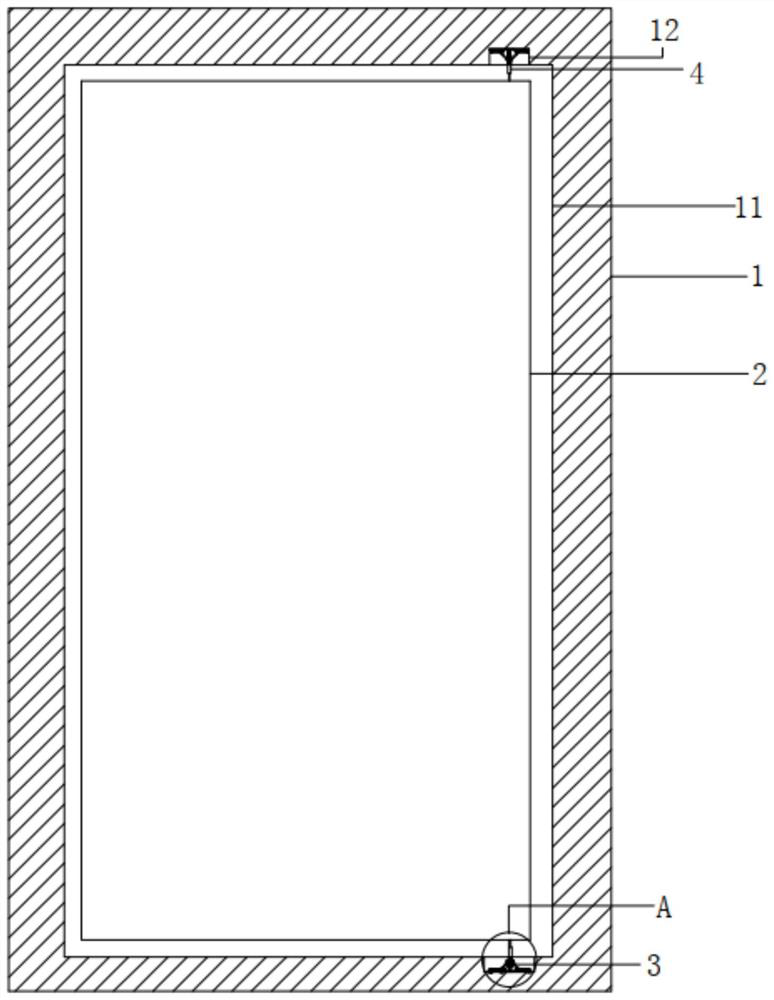
[0023] see Figure 1 to Figure 3 , the figure shows a prefabricated door shaft installation structure provided by Embodiment 1 of the present invention, mainly provided with a wall 1 and a door panel 2, the wall 1 is provided with an installation hole 11, and the door panel 2 is rotatably connected to the installation hole 11 Inside, the top of the mounting hole 11 is provided with a first rotating part 3, the bottom of the mounting hole 11 is provided with a second rotating part 4, one end of the door panel 2 is rotatably connected to the first rotating part 3, and the other end of the door panel 2 is rotatably connected to the On the second rotating part 4, the first rotating part 3 has the same structure as the second rotating part 4, the first rotating part 3 includes a first connecting rod 31, a first spring 32 is arranged in the first connecting rod 31, and a first spring 32 A support plate 33 is provided, a support rod 34 is installed on the support plate 33, one end of...

Embodiment 2

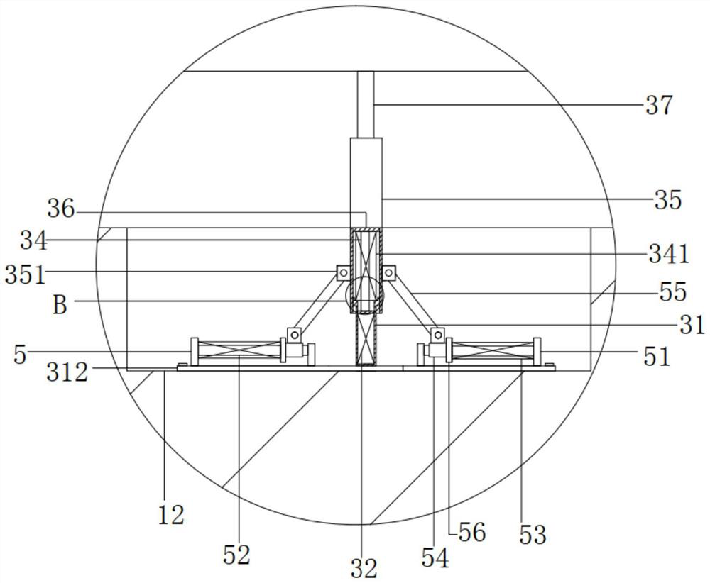
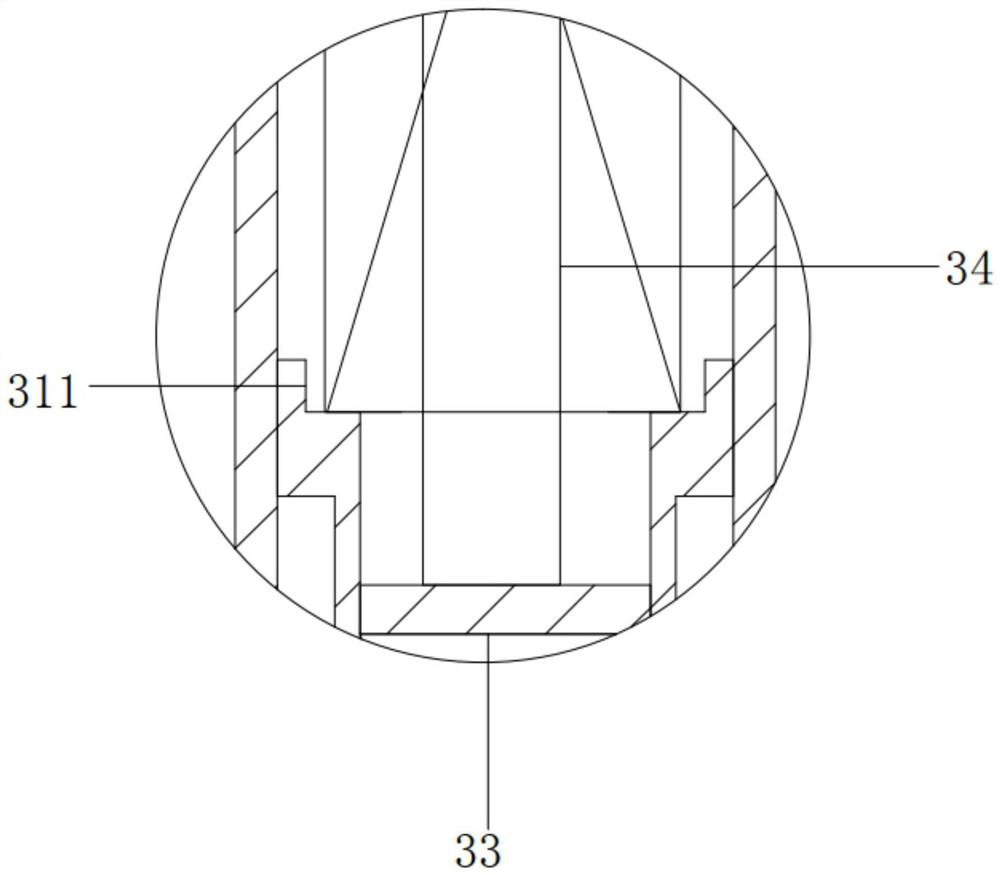
[0030] see Figure 1 to Figure 3 , the figure shows an assembled door shaft installation structure provided by Embodiment 2 of the present invention. On the basis of the above-mentioned embodiments, this embodiment further makes the following technical solutions as improvements: the support rod 34 A second spring 341 is sleeved, one end of the second spring 341 is connected to the first baffle 36, and the other end of the second spring 341 is connected to the first connecting rod 31; the first connecting rod 31 is provided with a stepped surface 311 , the end of the second spring 31 is connected to the stepped surface 311 . Through the setting of the above structure, the second spring 341 can play a buffering role, further preventing the door from sinking axially into the wall.

Embodiment 3

[0032] see Figure 1 to Figure 3 , the figure shows an assembled door shaft installation structure provided by the third embodiment of the present invention. On the basis of the above-mentioned embodiments, this embodiment further makes the following technical solutions as improvements: the first connecting rod The bottom of 31 is connected with mounting plate 312, and mounting plate 312 is provided with two supporting parts 5, and two supporting parts 5 are symmetrically arranged on the opposite sides of first connecting rod 31; block 51, a slide bar 52 is provided between the two supporting blocks 51, a third spring 53 is sleeved on the slide bar 52, a slide block 54 is slidably connected on the slide bar 52, and the slide block 54 is connected to the end of the third spring 53 In contact, the slider 54 is connected with a second connecting rod 55 , and the opposite end of the second connecting rod 55 is connected with the first rotating shaft 35 . Through the setting of th...


PUM


Abstract

The invention provides an assembly type door shaft mounting structure. The structure comprises a wall body and a door board, wherein a mounting hole is formed in the wall body, the door board is rotatably connected into the mounting hole, a first rotating component is arranged at the top of the mounting hole, a second rotating component is arranged at the bottom of the mounting hole, one end of the door board is rotatably connected to the first rotating component, the other end of the door board is rotatably connected to the second rotating component, and the first rotating component and the second rotating component are the same in structure; and the first rotating component comprises a first connecting rod, a first spring is arranged in the first connecting rod, a supporting plate is arranged on the first spring, a supporting rod is mounted on the supporting plate, one end of a first rotating shaft is arranged on the first connecting rod in a sleeving mode, a first baffle is arrangedin the first rotating shaft, the bottom of the first baffle is connected with the supporting rod, and the other end of the first rotating shaft is rotationally connected with a second rotating shaft.According to the structure, the problem that a fire exit door is inconvenient to open due to the fact that a door shaft sinks into a wall body can be effectively solved.

Description

technical field [0001] The invention relates to a door shaft, in particular to an assembled door shaft installation structure. Background technique [0002] Prefabricated decoration is a new form of decoration construction in recent years. As the name implies, prefabricated decoration is to complete the production of various parts and components required for decoration in the factory, and then transport them to the decoration site for assembly and installation, eliminating the need for traditional decoration on-site measurement and cutting of various parts and components. The construction is simpler and more convenient, which can greatly improve the construction efficiency of the decoration site, and the construction site is more tidy and beautiful, and will not produce too much decoration material waste. It is a more green and environmentally friendly form of decoration construction. [0003] At present, the concealed fire doors are connected to the wall through door shaft...

Claims


Application Information

Patent Timeline
IPC IPC(8): E05D7/081E05F5/08
CPCE05D7/081E05F5/08E05Y2900/132
Inventor 陆晓朋黄强王雨马子腾张海龙孙玲燕耿燕鲁迎周克标
Owner GOLD MANTIS FINE DECORATION TECH SUZHOU CO LTD
Why Eureka
Try Eureka