Glass fiber reinforced plastic cable bridge and cover plate fastening device thereof

A cable bridge and fastening device technology, applied in the direction of electrical components, etc., can solve the problems of poor fastening effect, cumbersome disassembly and assembly, etc., and achieve the effect of good fastening effect and convenient disassembly and installation

Active Publication Date: 2021-01-19
ANHUI HUAXI ELECTRIC POWER TECH CO LTD
View PDF13 Cites 2 Cited by
  • Summary
  • Abstract
  • Description
  • Claims
  • Application Information

AI Technical Summary

Problems solved by technology

[0003] There are many kinds of materials for cable trays, and fiberglass is one of them. When installing cable trays outdoors, a cover plate is usually installed on the top of the cable tray. The cover plate is used to prevent direct sunlight on the cables and reduce the outdoor environment. For the impact on the cable, install the cable tray indoors, and use the cover to block the accumulation o

Method used


Image

  • Glass fiber reinforced plastic cable bridge and cover plate fastening device thereof
  • Glass fiber reinforced plastic cable bridge and cover plate fastening device thereof
  • Glass fiber reinforced plastic cable bridge and cover plate fastening device thereof

Examples


Embodiment 1

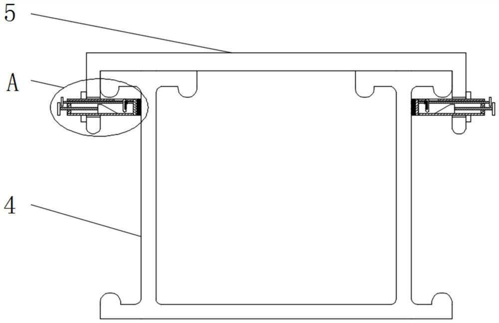
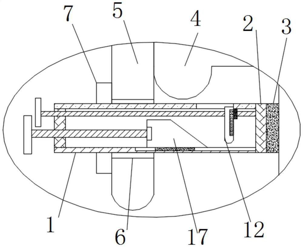
[0031] see Figure 1-7 According to an embodiment of the present invention, a fastening device for a FRP cable tray and its cover plate includes a sleeve 1, and one end of the sleeve 1 is fixedly connected with a sealing plate 2, and the sealing plate 2 is far away from the One end of the sleeve 1 is fixedly connected with a rubber pad 3, the rubber pad 3 is in contact with the cable tray 4, the top of the cable tray 4 is provided with a cover plate 5, and the side wall of the cover plate 5 is provided with a through hole 6, The sleeve 1 runs through the through hole 6, the outer surface of the sleeve 1 is threaded to the limit ring 7, and the outer wall of the sleeve 1 is provided with lines that can be threaded to the limit ring 7;

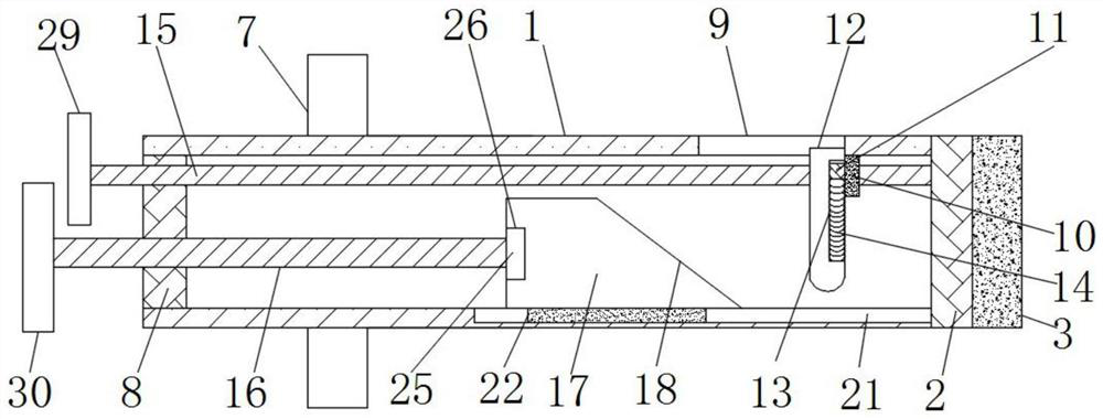
[0032] One end of the sleeve 1 away from the sealing plate 2 is fixedly connected with a sealing plate 2 8, and a movable opening 9 is formed on one side of the sleeve 1, and a movable opening 9 is arranged inside the sleeve 1 near the movable o...

Embodiment 2

[0036] see Figure 2-4 , the inner wall of the sleeve 1 is opened with a limiting slot 19 near the movable block 10, and the movable block 10 is fixedly connected with a limiting block 120 near the limiting slot 19, and the limiting block 120 Located in the limiting groove one 19 and matched with the limiting groove one 19, the limiting piece one 20 and the limiting groove one 19 can limit the movable block 10 so that the movable block 10 does not follow the movement of the screw rod one 15. Rotating and moving, the inner wall of the sleeve 1 is provided with a limiting groove 2 21 near the pushing block 17, and the pushing block 17 is fixedly connected with a limiting block 2 22 near the limiting groove 21, and the limiting Block two 22 is positioned in described limit groove two 21 and matches with described limit groove two 21, and limit block two 22 and limit groove two 21 can carry out position-limiting operation to pushing block 17, avoid pushing block 17 due to Screw I...

Embodiment 3

[0038] see image 3 with Image 6, the movable mechanism one includes a round hole one 23 and a bearing one 24, the surface of the sealing plate one 2 has a round hole one 23, the inner wall of the round hole one 23 is fixedly connected with a bearing one 24, and the screw rod one 15 Fixedly connected with the inner wall of the bearing one 24, the moving mechanism one can realize the flexible connection between the screw rod one 15 and the sealing plate one 2, the moving mechanism two includes the bearing two 25 and the round hole two 26, and the pushing block 17 is far away from the One end of the moving block 12 has a circular hole 26, the inner wall of the circular hole 26 is fixedly connected with a bearing 25, the screw 16 is fixedly connected with the inner wall of the bearing 25, and the movable mechanism 2 can realize screw Active connection between two 16 and the pushing block 17.


PUM


Abstract

The invention discloses a glass fiber reinforced plastic cable bridge and a cover plate fastening device thereof. The fastening device comprises a sleeve, one end of the sleeve is fixedly connected with a first sealing plate, the first sealing plate is fixedly connected with a rubber pad, the rubber pad makes contact with the cable bridge, and the top of the cable bridge is provided with a cover plate; a second sealing plate is fixedly connected to the end, away from the first sealing plate, of the sleeve; a movable opening is formed in one side of the sleeve; a movable block is arranged at the position, close to the movable opening, in the sleeve; a fixed block is fixedly connected to the middle of the movable block; a moving block is arranged on the side, close to the fixed block, of themovable block; one side of the movable block is in threaded connection with a first screw rod, one end of the first screw rod is connected with the first sealing plate through a first movable mechanism, the other end of the first screw rod penetrates through the second sealing plate, and a pushing block is arranged on the side, away from the movable opening, in the sleeve. The cable bridge has the beneficial effect that the cover plate can be fastened on the cable bridge.

Description

technical field [0001] The invention relates to the technical field of cable bridges, in particular to a fastening device for a fiberglass cable bridge and its cover. Background technique [0002] Cable trays are divided into trough type, tray type, ladder type, grid type and other structures, and are composed of brackets, supporting arms and installation accessories. The bridge frame in the building can be erected independently, or attached to various buildings (structures) and pipe gallery supports. [0003] There are many kinds of materials for cable trays, and fiberglass is one of them. When installing cable trays outdoors, a cover plate is usually installed on the top of the cable tray. The cover plate is used to prevent direct sunlight on the cables and reduce the outdoor environment. For the impact on the cable, install the cable tray indoors, and use the cover to block the accumulation of dust and the interference of other liquids. Therefore, the cover is more impor...

Claims


Application Information

Patent Timeline
IPC IPC(8): H02G3/04
CPCH02G3/0437H02G3/0418
Inventor 张文冰侯尽然李陆军袁超许春雷龚盼盼张志刚蒋跃跃翟慧阳
Owner ANHUI HUAXI ELECTRIC POWER TECH CO LTD
Why Eureka
Try Eureka