Trademark rubbing equipment for shoe boxes
A trademark and equipment technology, applied in printing, stamping, etc., can solve the problem of not being able to improve the standardization of the stamping position, achieve the effect of standardizing the stamping position, reducing the workload, and making it difficult to move
- Summary
- Abstract
- Description
- Claims
- Application Information
AI Technical Summary
Problems solved by technology
Method used
Image

Examples
Embodiment 1
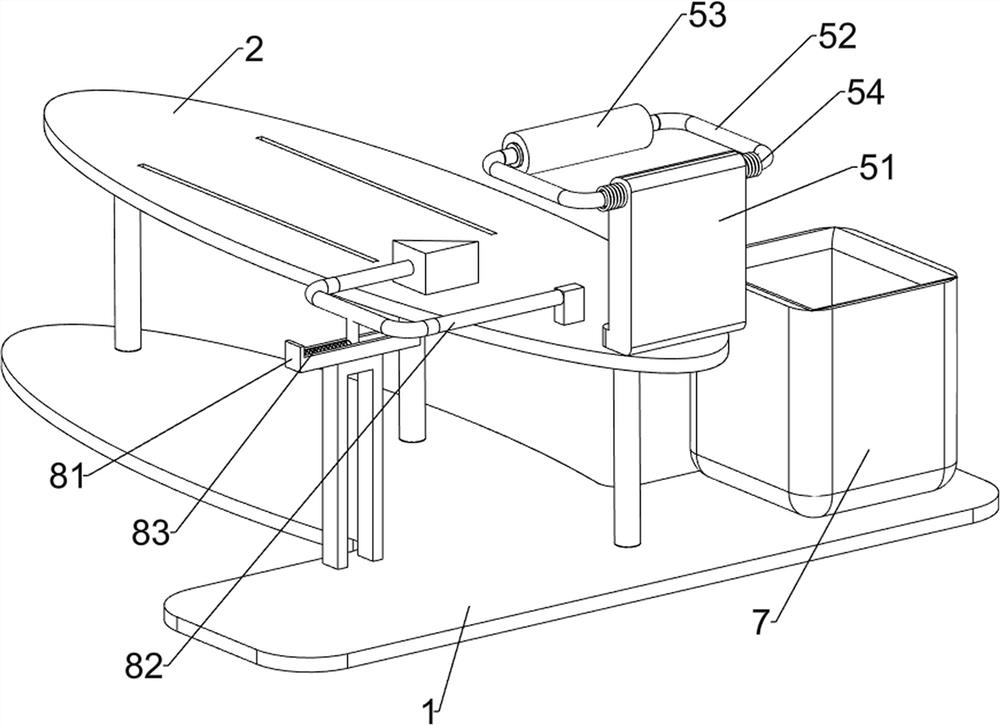
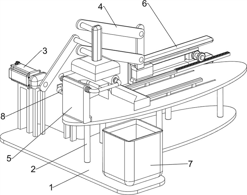
[0026] A shoe box trademark rubbing equipment, such as figure 1 and figure 2 As shown, it includes a bottom plate 1, a support frame 2, a servo motor 3, a labeling mechanism 4, a feeding mechanism 5 and a clamping mechanism 6. Five support frames 2 are uniformly arranged on the bottom plate 1, and the middle of the support frame 2 is slidingly designed. There is a clamping mechanism 6, a superscript mechanism 4 is provided on the left side of the support frame 2, a feeding mechanism 5 is provided on the front side of the support frame 2, and a servo motor 3 is installed on the left side of the base plate 1.
[0027] First place the shoe carton to be printed on the support frame 2, and then turn on the servo motor 3, the rotation of the output shaft of the servo motor 3 will drive the operation of the superscripting mechanism 4, thereby driving the operation of the feeding mechanism 5 and the clamping mechanism 6 After the printing is completed, the servo motor 3 is turned of...
Embodiment 2
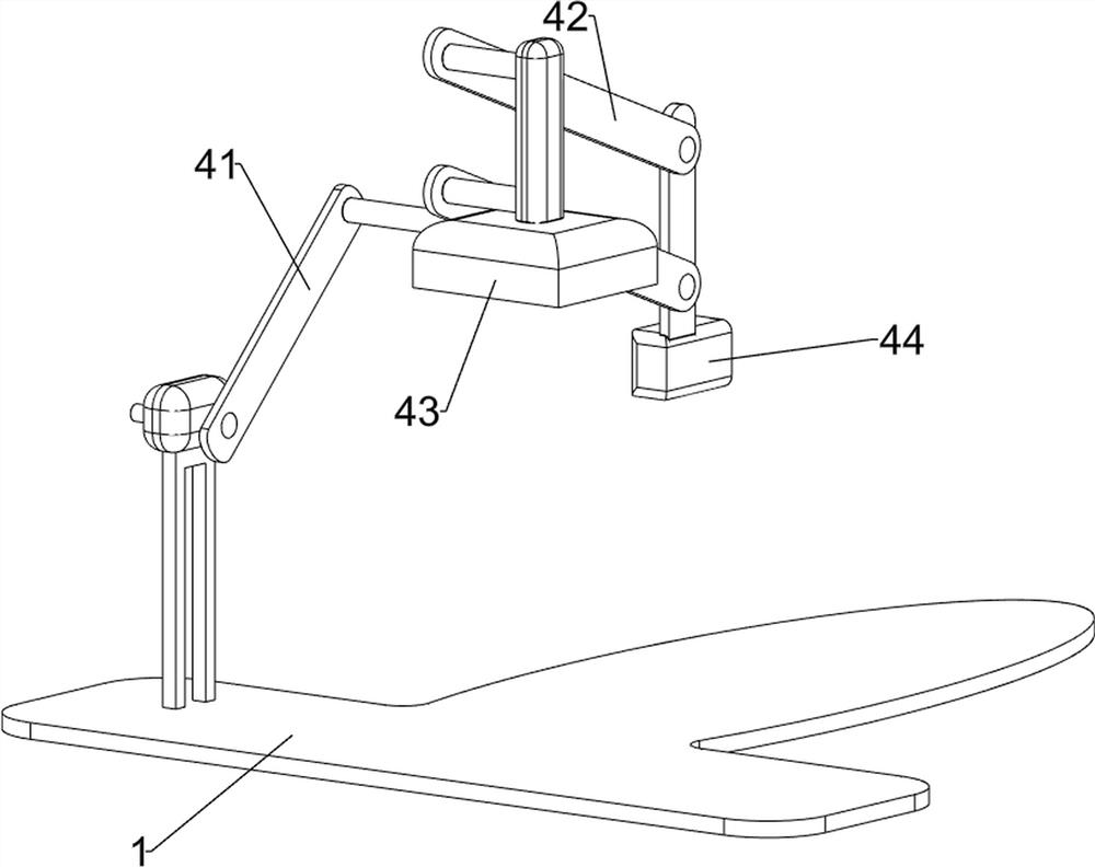
[0029] On the basis of Example 1, such as image 3 , Figure 4 and Figure 5 As shown, the superscripting mechanism 4 includes a connecting rod assembly 41, a swing rod 42, a trademark print 43 and a slide block 44, and the output shaft of the servo motor 3 is provided with a connecting rod assembly 41, and the right side of the connecting rod assembly 41 is rotated. Fork 42 is arranged, and the sliding type on the left side of bracing frame 2 is provided with slide block 44, and slide block 44 top is connected with fork 42 rotatably, and fork 42 right side rotatably is provided with trademark printing 43.
[0030] The output shaft of the servo motor 3 will rotate repeatedly in the range of 60°, and drive the swing rod 42 to swing, thereby driving the swing rod 42 to swing up and down, and then driving the slider 44 to move back and forth and the trademark printed piece 43 to move up and down, so reciprocating , under the cooperation of the feeding mechanism 5, the printing ...
Embodiment 3
[0036] On the basis of Example 2, such as Figure 5 As shown, a blanking mechanism 8 is also included. The upper left front side of the bottom plate 1 is provided with a blanking mechanism 8. The blanking mechanism 8 includes a mounting plate 81, a push rod 82 and an elastic member 83. A mounting plate 8 is provided on the left front side of the bottom plate 1. Plate 81 , on the mounting plate 81 is slidingly provided with a push rod 82 , the left side of the push rod 82 is provided with an elastic member 83 , and the left side of the elastic member 83 is connected to the mounting plate 81 .
[0037]When the wedge-shaped clamp block 65 moves forward and contacts the push rod 82, it will drive the push rod 82 to move to the left, and the elastic member 83 is in a compressed state. When the wedge-shaped clamp block 65 moves backward, it will no longer contact the push rod 82 Finally, the elastic member 83 resets from the compressed state, which will drive the push rod 82 to move...
PUM
 Abstract
Description
Claims
Application Information
 - R&D
- Intellectual Property
- Life Sciences
- Materials
- Tech Scout
- Unparalleled Data Quality
- Higher Quality Content
- 60% Fewer Hallucinations
Browse by: Latest US Patents, China's latest patents, Technical Efficacy Thesaurus, Application Domain, Technology Topic, Popular Technical Reports.
© 2025 PatSnap. All rights reserved.Legal|Privacy policy|Modern Slavery Act Transparency Statement|Sitemap|About US| Contact US: help@patsnap.com