
A hydraulic control valve for real-time detection of flow velocity

A hydraulic control valve, real-time detection technology, applied in valve device, valve details, valve shell structure and other directions, can solve the problems of reducing water quality, detecting water pressure, no flow rate, etc., to ensure stability, ensure cleanliness, and improve reliability. sexual effect

Active Publication Date: 2022-07-01
CHINA VALVE HLDG (GRP) CO LTD
View PDF0 Cites 0 Cited by
  • Summary
  • Abstract
  • Description
  • Claims
  • Application Information

AI Technical Summary

Problems solved by technology

[0003] When the existing hydraulic control valve is in use, there is no function of detecting the flow rate, which makes it impossible to detect the water pressure and the water volume of the water storage tank according to the flow rate of the water flow, so that it often needs to be judged by other devices when in use. The amount of water is very troublesome. At the same time, the existing device does not have a function of filtering, pressure relief, and dust removal, so that the particulate matter in the water flow is discharged to the water receiving position along with the water flow, thereby reducing the water quality and affecting the use. It is not conducive to the flow of water. transportation

Method used


Image

  • A hydraulic control valve for real-time detection of flow velocity
  • A hydraulic control valve for real-time detection of flow velocity
  • A hydraulic control valve for real-time detection of flow velocity

Examples


Embodiment Construction

[0030] In order to make the objectives, technical solutions and advantages of the present invention clearer, the present invention will be further described in detail below with reference to the specific embodiments and the accompanying drawings. It should be understood that these descriptions are exemplary only and are not intended to limit the scope of the invention. Also, in the following description, descriptions of well-known structures and techniques are omitted to avoid unnecessarily obscuring the concepts of the present invention.

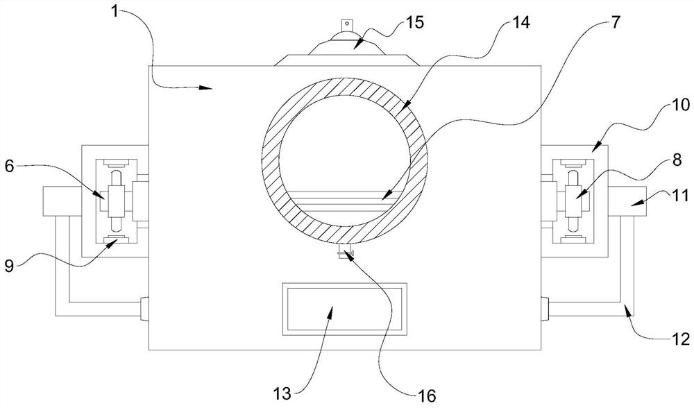
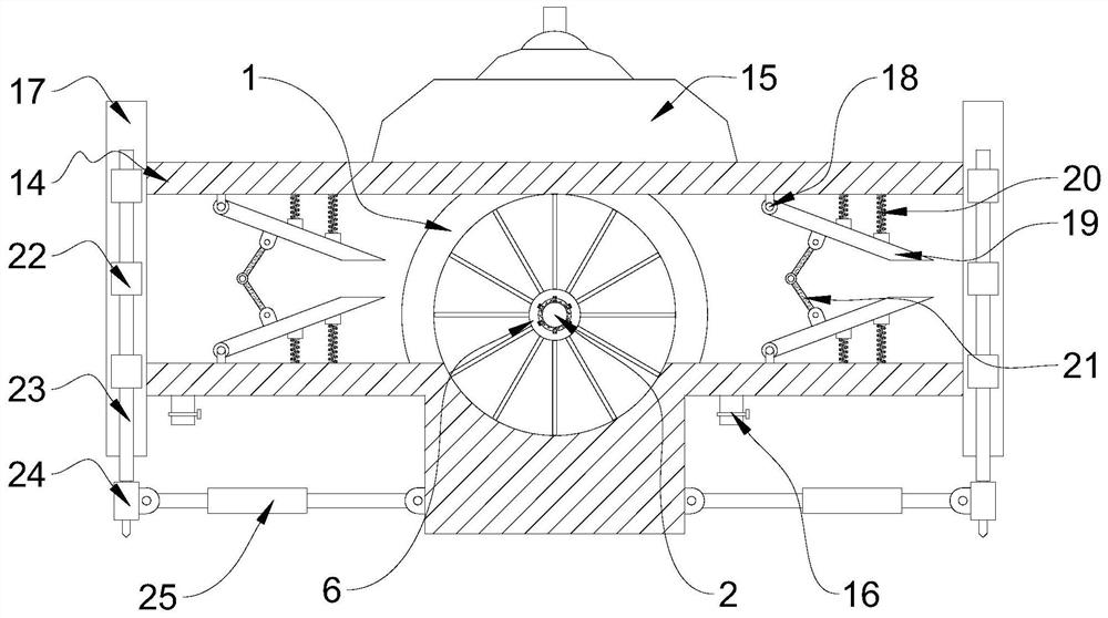
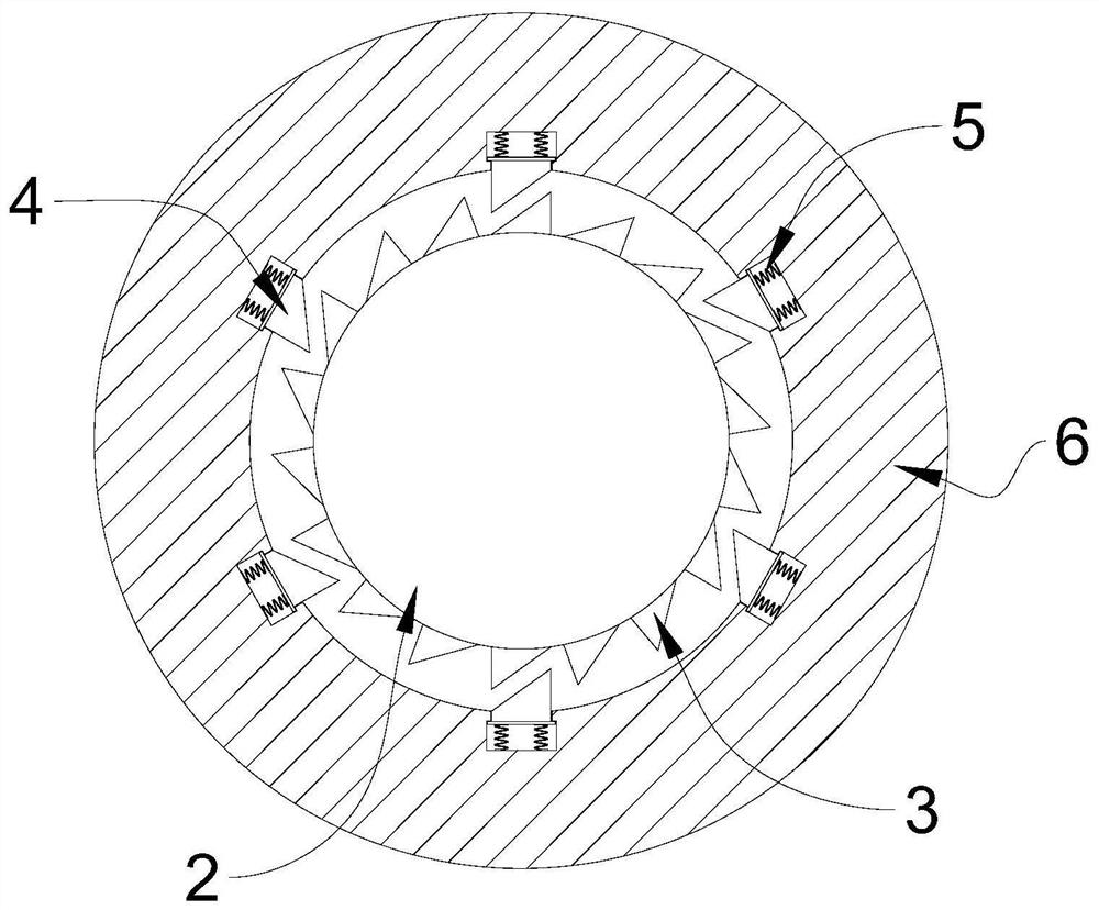
[0031] like Figure 1-5 As shown, a hydraulic control valve for real-time detection of flow velocity is provided, including a monitoring housing 1, a fixed shaft 2 is fixedly sleeved inside the monitoring housing 1, an outer rotating sleeve 6 is movably connected to the fixed shaft 2, and the outer rotating sleeve The outer side of 6 is fixedly installed with a detection blade 7, the two ends of the outer rotating sleeve 6 penetrate throug...


PUM


Abstract

The invention belongs to the field of hydraulic control valves, in particular to a hydraulic control valve for real-time detection of flow velocity. , a detection blade is fixedly installed on the outer side of the outer rotating sleeve, the two ends of the outer rotating sleeve penetrate through the side wall of the monitoring casing and are fixedly sleeved with a bidirectional signal transmitting head, and the monitoring casing is close to the position of the outer rotating sleeve The external fixing frame is fixedly installed. By arranging ratchet teeth on the outer side of the fixed shaft, and setting meshing teeth on the inner side of the outer rotating sleeve to mesh with the ratchet teeth, the outer rotating sleeve can only rotate clockwise relative to the fixed shaft, avoiding the situation of backflow and ensuring the smooth operation of the device. At the same time, it also prevents the counterclockwise rotation of the outer rotating sleeve when driving the rotation of the two-way signal transmitting head, which leads to the detection error of the sensing head, making the linkage between the structures more reliable and accurate.

Description

technical field [0001] The invention relates to the field of hydraulic control valves, in particular to a hydraulic control valve for real-time detection of flow velocity. Background technique [0002] Hydraulic control valve is a general term, a type of automatic control valve composed of a main valve and its external needle valve, guide valve, etc. The working state of hydraulic control valve is generally in the usual state, normally open state, floating state, It mainly depends on the adjustment between the main valve and the needle valve or pilot valve to control the water flow state. [0003] When the existing hydraulic control valve is in use, there is no function of detecting the flow rate, so that it is impossible to detect the water pressure and the water volume of the water storage tank according to the flow rate of the water flow, so that when in use, it is often necessary to judge by other devices. The amount of water is very troublesome. At the same time, the e...

Claims


Application Information

Patent Timeline
Patent Type & Authority Patents(China)
IPC IPC(8): F16K37/00F16K27/00B01D35/04B01D29/94
CPCF16K37/0091F16K27/00B01D35/04B01D29/94
Inventor 陈春健陈志文
Owner CHINA VALVE HLDG (GRP) CO LTD
Learn More