Gradienter for constructional engineering measurement

A construction engineering and spirit level technology, which is applied in the direction of measuring devices, measuring inclinations, instruments, etc., can solve the problems of offset placement of level instruments, lower measurement accuracy, unfavorable construction, etc., to prolong service life, ensure accuracy, and facilitate measurement Effect

Pending Publication Date: 2021-01-22
TONGREN POLYTECHNIC COLLEGE
4 Cites 0 Cited by

AI-Extracted Technical Summary

Problems solved by technology

[0002] Engineering survey refers to the general term for all surveying and mapping work in engineering construction, including various surveying work carried out in the stages of engineering construction survey, design, construction and management; engineering surveying is divided into engineering control surveying in the survey and design stage according to its work sequence and nature And topographic survey, construction survey and equipment installation survey in the construction stage, completion survey in the complet...

Method used

Further, described universal wheel 2 is installed and connected with base 1 via assembly seat 4, and the cross section of assembly seat 4 becomes T-shaped, and one end of assembly seat 4 away from universal wheel 2 extends to the inside of base 1 and A vertical damping spring 20 is connected with the base 1 to reduce the vibration during the movement of the device.
In order to improve the working effect of shock absorbing spring 20, avoid the situation that assembly seat 4 and base 1 get stuck, the present embodiment improves on the basis of embodiment 1, and improvement is: described assembly seat 4 Rollers are installed on both sides of the base to fit the inner wall of the base 1, so that the sliding of the assembly seat 4 is smoother, and the shock absorption effect of the shock-absorbing spring 20 is improved.
Please refer to Fig. 1-4, a kind of spirit level that construction engineering surveys, comprises base 1, and the upper end surface of described base 1 is fixedly connected with mounting frame 5, is fixedly connected between mounting frame 5 and base 1 There are reinforcing ribs, and the base plate 7 is movably installed on the mounting frame 5. The upper part of the base plate 7 away from the mounting frame 5 is fixedly connected with the mounting base 11, and the lower end of the mounting base 11 is fixedly connected with the base plate 7. A rib...

Abstract

The invention discloses a gradienter for constructional engineering measurement. The gradienter comprises a base, wherein a mounting frame is fixedly connected to the upper end face of the base, a base plate is mounted on the mounting frame, a mounting base is fixedly connected to the upper portion of the side, deviating from the mounting frame, of the base plate, a rack is assembled at the upperend of the base plate through a rotating shaft, and a gradienter body is mounted on the bottom plate. According to the gradienter for constructional engineering measurement, a positioning block is arranged to be matched with scale marks, so that a user can conveniently check whether the placement position of the gradienter deviates or not in time; moreover, the gradienter can deflect by rotating the worm until the gradienter and the center line of the scale line are positioned on the same vertical line, so that the measurement precision is ensured; the base plate can be driven to lift by rotating a hand wheel, so that the placement position of the gradienter is changed; in addition, a damping spring is arranged between an assembling base and the base, so that the gradienter is more stablewhen moving on an uneven road surface.

Application Domain

Incline measurement

Technology Topic

Structural engineeringMechanical engineering +2

Image

  • Gradienter for constructional engineering measurement
  • Gradienter for constructional engineering measurement
  • Gradienter for constructional engineering measurement

Examples

  • Experimental program(2)

Example Embodiment

[0019] Example 1
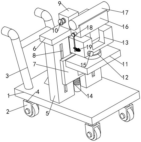
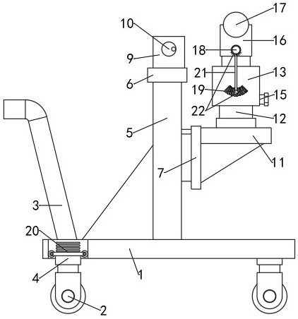
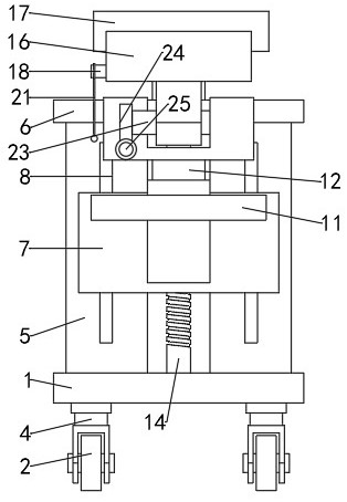
[0020] see Figure 1-4 , a level used for construction engineering measurement, comprising a base 1, the upper end surface of the base 1 is fixedly connected with a mounting frame 5, a reinforcing rib is fixedly connected between the mounting frame 5 and the base 1, and the mounting frame 5 is movable The base plate 7 is installed, and the upper part of the side of the base plate 7 facing away from the mounting frame 5 is fixedly connected with the mounting base 11, and the lower end of the mounting base 11 is fixedly connected with the base plate 7. , the cross-section of the frame 13 is concave, and the frame 13 is rotated through the assembly shaft 23 to be equipped with a base plate 16, and a level 17 is installed on the base plate 16; one side of the base plate 16 is fixedly connected with an assembly rod 18, and the assembly rod 18 is connected via The wire rope 21 is connected with a positioning block 19; one side of the frame 13 and the base plate 16 is provided with a scale line 22 in a uniform arc-shaped area, and the positioning block 19 is suspended on one side of the scale line 22, so as to observe the device Whether it is placed horizontally; one end of the assembly shaft 23 extends to the inside of the frame 13 and is equipped with a worm wheel 24, and the inside of the frame 13 is equipped with a worm 25, the worm 25 is located below the worm wheel 24 and is in transmission connection with the worm wheel 24. One end extends to the outside of the frame 13 and is fixedly connected with a hexagonal head 15, so as to adjust the placement position of the level 17 and improve the measurement accuracy.
[0021] Further, the mounting frame 5 is equipped with a vertical lifting screw 14, and the mounting frame 5 is provided with two non-through chute 8 at intervals, and the two chutes 8 are symmetrically distributed on both sides of the lifting screw 14. , the base plate 7 and the lifting screw rod 14 are driven and installed and slidably installed with the chute 8; the upper end surface of the fixed base 6 is fixedly installed with a drive chamber 9, and a horizontal drive shaft 27 is installed in the drive chamber 9, and the drive shaft 27 is assembled Drive wheel 28 is arranged, and one end of drive shaft 27 extends to the outside of drive cavity 9 and is fixedly connected with handwheel 10, and one end of lifting screw 14 extends to the inside of drive cavity 9 and is equipped with interlocking wheel 26, and interlocking wheel 26 and driving The wheels 28 are driven and engaged to drive the base plate 7 up and down.
[0022] Further, one end of the rotating shaft 12 extends to the inside of the mounting base 11 and is connected with a rotary motor for transmission to adjust the measurement angle of the level 17 .
[0023] Further, the lower end of the base 1 is evenly equipped with a plurality of universal wheels 2, and a locking switch is arranged on the universal wheels 2, and a push rod 3 is fixedly connected to one side of the upper end surface of the base 1.
[0024] Further, the universal wheel 2 is installed and connected to the base 1 through the assembly seat 4, the cross section of the assembly seat 4 is T-shaped, and the end of the assembly seat 4 away from the universal wheel 2 extends to the inside of the base 1 and is connected to the base 1 is connected with a vertical damping spring 20 to reduce the vibration during the movement of the device.
[0025] Further, the outer periphery of the push rod 3 is provided with a rubber anti-slip sleeve, so that the operator can hold the push rod 3 to push the device to move and avoid slipping.
[0026] The working principle of this embodiment is:
[0027] In actual use, place the device in a designated area for fixing, and observe whether the positioning block 19 is suspended at the middle position of the scale line 22 at the frame 13. If so, no adjustment is required. If it is not at the middle position, turn the hexagon head 15, so that the worm gear 24 and the worm screw 25 are in transmission engagement, so that the assembly shaft 23 rotates, and the position of the scale line 22 on the bottom plate 16 is offset until the center line of the steel wire rope 21 coincides with the midline of the scale line 22 on the bottom plate 16; shake the handwheel 10 is used to drive the lifting screw 14 to run, thereby changing the measurement height of the level 17, which is convenient for adjustment, and the rotary motor connected to the rotating shaft 12 can drive the level 17 to rotate to expand the measurement range.

Example Embodiment

[0028] Example 2
[0029] In order to improve the working effect of the shock absorbing spring 20 and avoid the jamming of the assembly seat 4 and the base 1, this embodiment is improved on the basis of the embodiment 1, and the improvements are: the two sides of the assembly seat 4 The rollers fitted are attached to the inner wall of the base 1 so that the sliding of the assembly seat 4 is smoother and the damping effect of the damping spring 20 is improved.

PUM

no PUM

Description & Claims & Application Information

We can also present the details of the Description, Claims and Application information to help users get a comprehensive understanding of the technical details of the patent, such as background art, summary of invention, brief description of drawings, description of embodiments, and other original content. On the other hand, users can also determine the specific scope of protection of the technology through the list of claims; as well as understand the changes in the life cycle of the technology with the presentation of the patent timeline. Login to view more.

Similar technology patents

Knowledge base supported spatial database design method

InactiveCN101477549AGuaranteed accuracyAchieve an optimized design
Owner:CHINESE ACAD OF SURVEYING & MAPPING

Log backup method and device and smart card

InactiveCN102567146AGuaranteed accuracy
Owner:BEIJING WATCH DATA SYST

Train tracking method based on information redundancy

ActiveCN104149822AGuaranteed accuracyKeep Tracking
Owner:NARI TECH CO LTD

Classification and recommendation of technical efficacy words

  • Easy to measure
  • Guaranteed accuracy

Small mechanical part shape and position error detection device and detection method thereof

InactiveCN104330024AEasy to measureEnable multiple detection
Owner:济宁中科智能科技有限公司

Method for measuring gradient of tower

Owner:BEIJING GOLDWIND SCI & CREATION WINDPOWER EQUIP
Why Eureka
Try Eureka