High-efficiency energy-saving relay

A high-efficiency energy-saving, relay technology, applied in the direction of relays, electromagnetic relays, detailed information of electromagnetic relays, etc., can solve the problems that the relay cannot be damped, the relay cannot be placed in a safe position, and the relay is not easy to fix, so as to facilitate installation and disassembly. Fixed, easy to adjust, convenient shock absorption protection effect

Pending Publication Date: 2021-01-22
徐浩
View PDF9 Cites 2 Cited by
  • Summary
  • Abstract
  • Description
  • Claims
  • Application Information

AI Technical Summary

Problems solved by technology

[0004] The object of the present invention is to provide a high-efficiency energy-saving relay. By arranging a pressing column and a snap fit of the clamping column, the relay can be fixed in a box, which solves the problem that the traditional relay is not easy to fix; The problem that the relay cannot be damped; by setting the lifting bracket, it is convenient to adjust the height of the relay, which solves the problem that the existing device cannot place the relay in a safe position

Method used


Image

  • High-efficiency energy-saving relay
  • High-efficiency energy-saving relay
  • High-efficiency energy-saving relay

Examples


Embodiment 1

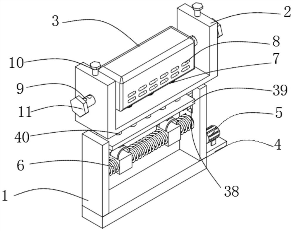
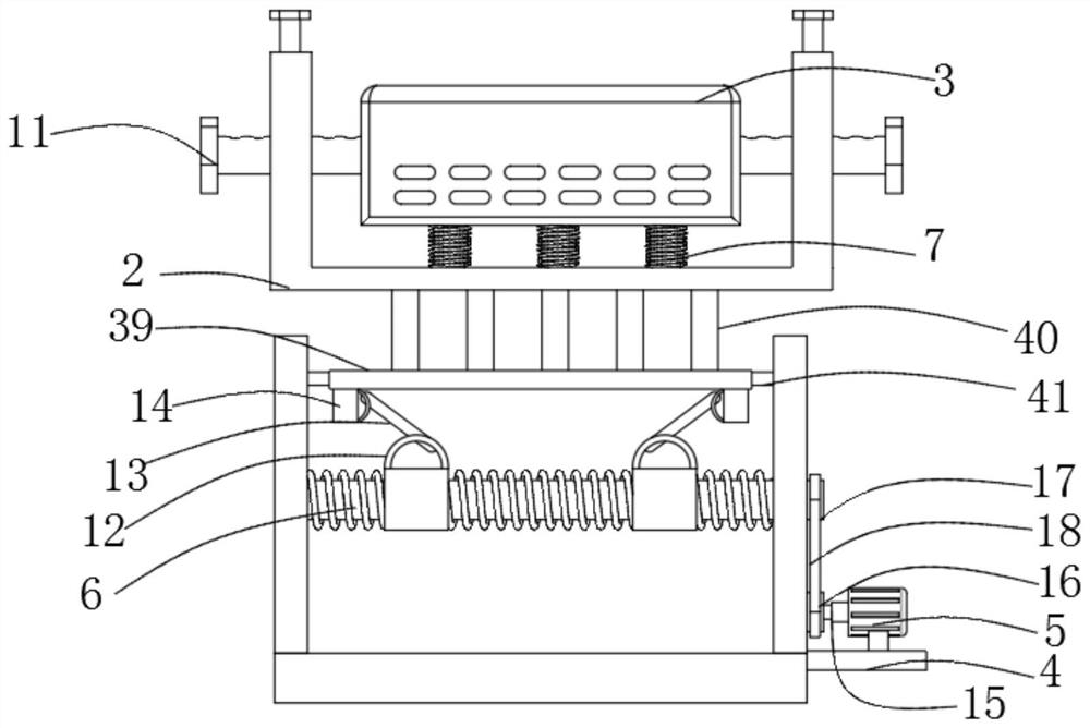
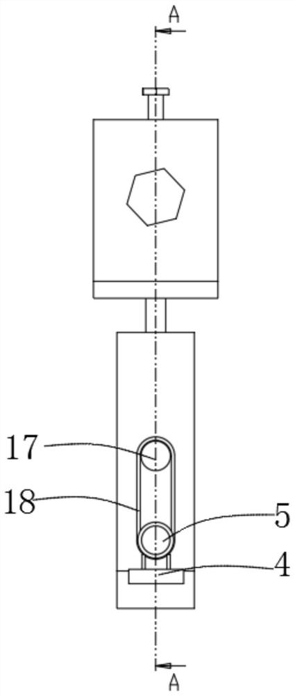
[0037] The following is a specific method of using a high-efficiency and energy-saving relay: first, adjust the height of the relay box 3, connect the driving motor 5 to the power supply, and the driving wheel 16 drives the driven wheel 17 to rotate through the rotating belt 18, and then drives the two-way threaded column 6 Rotation, when the two-way threaded column 6 rotates, it drives the movable screw sleeve 12 to move laterally, and then drives the moving rod 13 to move longitudinally, and further drives the moving block 14 to move longitudinally, and completes the adjustment of the height of the relay packing 3. According to the size of the relay packing 3 , move the pressing column, insert the clamping column 10 into the card slot 22 to complete the fixing of the relay box 3, and then connect the relay to the power supply.

Embodiment 2

[0039] It should be further explained that when the relay module 20 needs to be disassembled, by pressing the pressing plate 33, the first block 29 is pressed against the second block 30 so that it is completely compressed into the limiting groove 30, and then the installation The slide block 28 can be pulled out from the second installation groove 27 to complete the disassembly.


PUM


Abstract

The invention discloses a high-efficiency energy-saving relay, and relates to the technical field of relays. The relay comprises a lifting support, a mounting support and a relay box, bidirectional threaded columns are arranged on the two opposite side faces of the lifting support, movable threaded sleeves are arranged on the circumferential side faces of the bidirectional threaded columns, movable rods are connected to the upper surfaces of the movable threaded sleeves, and movable blocks are connected to one ends of the movable rods and connected with a lifting plate; the lifting plate is connected with an installation support through supporting rods, damping springs are arranged on the bottom face of the inner wall of the installation support, one ends of the damping springs are connected with the relay box, pressing columns are arranged on the two opposite side faces of the installation support, pressing plates are fixedly installed at one ends of the pressing columns, and clampingcolumns are arranged on the upper surfaces of side plates of the installation support. By arranging the pressing columns and the clamping columns to be clamped and matched, relay boxes of different sizes can be fixed conveniently; the damping springs are arranged, so that damping protection on relay box is facilitated; and the lifting support is arranged to facilitate height adjustment of the relay box.

Description

technical field [0001] The invention belongs to the technical field of relays, in particular to a high-efficiency energy-saving relay. Background technique [0002] Relay (English name: relay) is an electrical control device, which is an electrical appliance that causes the controlled quantity to undergo a predetermined step change in the electrical output circuit when the change of the input quantity (excitation quantity) meets the specified requirements. It has an interactive relationship between the control system (also known as the input loop) and the controlled system (also known as the output loop). Usually used in automatic control circuits, it is actually an "automatic switch" that uses a small current to control the operation of a large current. Therefore, it plays the role of automatic adjustment, safety protection, and conversion circuit in the circuit. [0003] Traditional relays are usually placed in a box for use. When the relay module is used, a large amount...

Claims


Application Information

Patent Timeline
Patent Type & Authority Applications(China)
IPC IPC(8): H01H50/04H01H50/12H01H50/14F16F15/067
CPCH01H50/047H01H50/12H01H50/14F16F15/067
Inventor 徐浩
Owner 徐浩
Why Eureka
Try Eureka