Multi-band antenna structure

A multi-band antenna and antenna structure technology, applied in the direction of antenna grounding switch structure connection, antenna, antenna parts, etc., can solve the problems of limited internal space of terminal equipment, multi-space structure, insufficient structural space of terminal equipment, etc., and achieve structural space The effect of small requirements, meeting network requirements, and low cost

Pending Publication Date: 2021-01-22
NUBIA TECHNOLOGY CO LTD
View PDF0 Cites 0 Cited by
  • Summary
  • Abstract
  • Description
  • Claims
  • Application Information

AI Technical Summary

Problems solved by technology

[0004] However, since the internal space of the terminal equipment is limited, and the 5G frequency band has high requirements on the layout of the antenna, there is no technical solution in the prior art that can meet the requirements of multiple frequency bands through one module, and the current The 5G frequency band antenna structure in the existing technology occupies a lot of space structure, which may cause the problem of insufficient structural space for terminal equipment

Method used


Image

  • Multi-band antenna structure
  • Multi-band antenna structure
  • Multi-band antenna structure

Examples


Embodiment 1

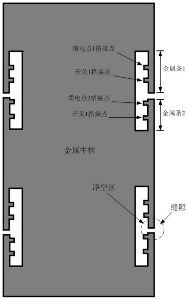
[0049] image 3 It is the first structural schematic diagram of the multi-band antenna structure of the present invention. This embodiment proposes a multi-band antenna structure. The antenna structure includes: four slots arranged on the metal frame of the terminal device, and the four slots are arranged in pairs on opposite sides of the metal frame. Two metal strips are arranged at the slot, and a feeding point and a switch bonding point are arranged in each of the metal strips.

[0050] Optionally, in this embodiment, in the normal holding posture of the terminal device, two slots are respectively provided on the metal frames on the left and right sides of the terminal device, wherein four slots are provided perpendicular to the left and right sides;

[0051] Optionally, in this embodiment, the width range of the four slots is 1-2mm;

[0052] Optionally, in this embodiment, four antenna units are formed by opening four slots on the metal frame of the terminal device;

[...

Embodiment 2

[0059] Figure 4 It is a second structural schematic diagram of the multi-band antenna structure of the present invention. Based on the above embodiment, in this embodiment, optionally, the four slots are arranged in pairs on the left and right sides of the metal frame, and are distributed axially symmetrically on the left and right sides.

[0060] Optionally, in this embodiment, a first metal strip and a second metal strip are arranged along the metal frame at the first slot among the four slots, and the first metal strip and the The middle area of ​​the second metal strip constitutes a clearance area.

[0061] Optionally, in this embodiment, four antenna units are formed by four slots and a metal frame. Wherein, the antenna unit 1 is taken as an example for illustration, and it can be understood that the antenna unit 2 , the antenna unit 3 and the antenna unit 4 can also implement the same function or combination in the same manner. Specifically, in the antenna unit 1, a ...


PUM


Abstract

The invention discloses a multi-band antenna structure, which comprises four slots formed in a metal frame of terminal equipment, wherein every two of the four slots are formed in the two opposite sides of the metal frame, two metal strips are arranged at each slot, and a feeding point and a switch lap joint point are arranged in each metal strip. According to the invention, a 5G multi-band antenna structure low in cost and small in structural space requirement is achieved, multiple antenna forms are achieved, coupling and interference of the two antennas in the same frequency band are reduced, and the network requirements of multiple frequency bands and multiple antennas are met.

Description

technical field [0001] The invention relates to the field of mobile communication, in particular to a multi-band antenna structure. Background technique [0002] In the prior art, with the rapid development of smart terminal equipment and basic network technologies, the popularity of 5G networks is also increasing. Among them, 5G network is the abbreviation of the fifth generation (5th Generation) mobile communication. At present, my country's three major operators have obtained the nationwide 5G medium and low frequency band test frequency license. From the perspective of the overall distribution, each region and operator Six main frequency bands n1 / n3 / n41 / n77 / n78 / n79 have been allocated, among which, n78: 3400MHz-3600MHz, China Telecom, China Unicom; n41: 2515MHz-2675MHz, China Mobile; n79: 4400MHz-4900MHz, China Mobile; n1: 1920M-2170M, China Telecom and China Unicom use spectrum sharing with LTE to enhance 5G coverage, which is also the main frequency band of 5G in the wo...

Claims


Application Information

Patent Timeline
Patent Type & Authority Applications(China)
IPC IPC(8): H01Q5/28H01Q1/22H01Q1/24H01Q1/50
CPCH01Q1/22H01Q1/241H01Q1/50H01Q5/28
Inventor 陈笛宋文宾
Owner NUBIA TECHNOLOGY CO LTD
Why Eureka
Try Eureka