Vibration module, vibration module control method and electronic device

An electronic device, vibration mode technology, applied in electrical components, generators/motors, piezoelectric effect/electrostrictive or magnetostrictive motors, etc., can solve problems such as high power consumption

Inactive Publication Date: 2021-01-22
TIANMA MICRO ELECTRONICS
5 Cites 0 Cited by

AI-Extracted Technical Summary

Problems solved by technology

[0002] In the prior art, the mobile terminal equipment provides a ringing function and a vibration function, and can send out a ringing or perform vibration to remind the user when receiving notification information or reminders...

Abstract

The invention discloses a vibration module, a vibration module control method and an electronic device. The vibration module comprises: a frame body provided with an accommodation cavity; a vibrationassembly arranged in the accommodation cavity, wherein a gap is formed between the vibration assembly and the frame body, and the vibration assembly comprises a multi-dimensional vibrator; and a piezoelectric buffer part filled in the gap between the frame body and the vibration assembly and used for converting mechanical vibration into electric energy, wherein the piezoelectric buffer part is electrically connected with the multi-dimensional vibrator so as to drive the multi-dimensional vibrator to vibrate. According to the invention, the piezoelectric buffering part is made of a piezoelectric material, due to the piezoelectric effect of the piezoelectric materials, when the piezoelectric materials are subjected to external impact and generate mechanical vibration, the mechanical vibration can be converted into electric energy, the electric energy generated by the piezoelectric buffering part drives the multi-dimensional vibrator to vibrate, and an extra power source does not need tobe arranged to supply power to the multi-dimensional vibrator, so that energy is saved; and the vibration module provided by the embodiment of the invention is suitable for the situation that chargingis inconvenient or electric power is insufficient, and the application range is wide.

Application Domain

Piezoelectric/electrostriction/magnetostriction machines

Technology Topic

PhysicsElectric energy +5

Image

  • Vibration module, vibration module control method and electronic device
  • Vibration module, vibration module control method and electronic device
  • Vibration module, vibration module control method and electronic device

Examples

  • Experimental program(1)

Example Embodiment

[0024]The features and exemplary embodiments of various aspects of the present invention will be described in detail below. In the following detailed description, many specific details are proposed in order to provide a comprehensive understanding of the present invention. However, it is obvious to those skilled in the art that the present invention can be implemented without some of these specific details. The following description of the embodiments is only to provide a better understanding of the present invention by showing examples of the present invention.
[0025]It should be noted that in this article, relational terms such as first and second are only used to distinguish one entity or operation from another entity or operation, and do not necessarily require or imply one of these entities or operations. There is any such actual relationship or order between. Moreover, the terms "include", "include" or any other variants thereof are intended to cover non-exclusive inclusion, so that a process, method, article or device including a series of elements not only includes those elements, but also includes those that are not explicitly listed Other elements of, or also include elements inherent to this process, method, article or equipment. If there are no more restrictions, the elements defined by the sentence "including..." do not exclude the existence of other identical elements in the process, method, article, or equipment that includes the elements.
[0026]In order to better understand the present invention, the following is combinedFigure 1 to Figure 14 The vibration module, control method, and electronic device according to the embodiments of the present invention will be described in detail.
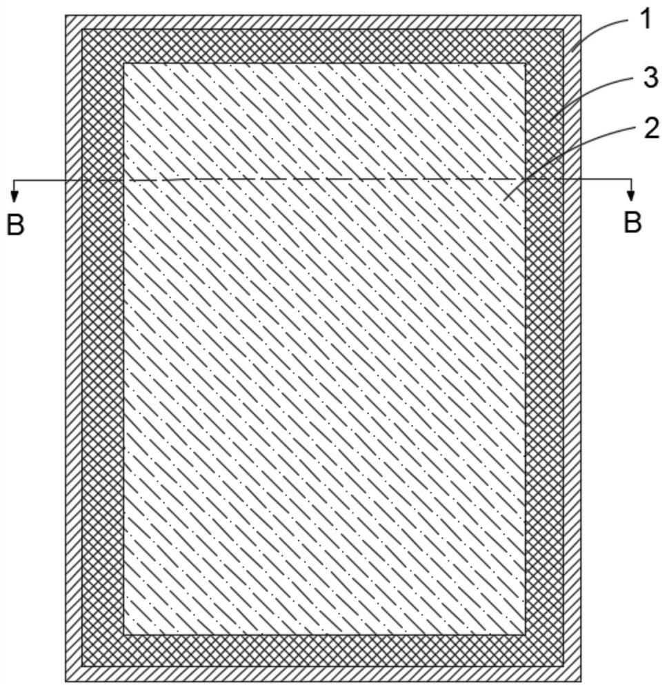
[0027]Please refer tofigure 1 withfigure 2 ,figure 1 Is a schematic structural diagram of a vibration module provided according to an embodiment of the present invention,figure 2 It is a kind offigure 1 Sectional view at section B-B in the middle. The embodiment of the present invention provides a vibration module for use in an electronic device, comprising: a frame body 1 having a accommodating cavity A; a vibration component 2 arranged in the accommodating cavity A and spaced from the frame body 1 to vibrate The assembly 2 includes a multi-dimensional vibrator 21; a piezoelectric buffer part 3, which is filled in the space between the frame 1 and the vibration assembly 2, for converting mechanical vibration into electric energy, and the piezoelectric buffer part 3 is electrically connected to the multi-dimensional vibrator 21 , To drive the multi-dimensional vibrator 21 to vibrate.
[0028]The vibration module provided by the embodiment of the present invention includes a frame 1, a vibration component 2, and a piezoelectric buffer part 3. The vibration module is fixed in the accommodating cavity A of the frame 1, and the vibration module includes a multidimensional vibrator 21. The multi-dimensional vibrator 21 specifically refers to a device capable of generating vibrations in multiple directions. The space between the frame 1 and the vibrating assembly 2 is filled with a piezoelectric buffer 3, and the piezoelectric buffer 3 can be used in the vibration mode. The group acts as a cushion when subjected to external shocks. On the other hand, the piezoelectric buffer 3 is made of piezoelectric material. Due to the piezoelectric effect of the piezoelectric material, when mechanical vibration is generated by external impact, the mechanical vibration can be converted into electrical energy. The piezoelectric buffer 3 The generated electric energy drives the multi-dimensional vibrator 21 to vibrate, and no additional power supply is required to power the multi-dimensional vibrator 21, which saves energy. In addition, the vibration module provided by the embodiment of the present invention is suitable for situations where charging is not convenient or the power is insufficient, and has a wide application range.
[0029]Specifically, an insulating layer 5 is wrapped around the outer circumference of the piezoelectric buffer part 3, and the piezoelectric buffer part 3 is connected to the vibration component 2 through a wire L1, so that the current generated by the piezoelectric buffer part 3 flows directly to the vibration component 2 to supply power to it. In order to avoid electric leakage, the conductive wire L1 can be passed through by providing a via hole or the like on the insulating layer 5.
[0030]SeeFigure 4 to Figure 6, The specific principle of the current generated by the piezoelectric buffer 3 is as follows, such asimage 3 As shown, when the piezoelectric buffer 3 is not subjected to external force, the crystal symmetry is low. When the piezoelectric buffer 3 is deformed due to mechanical vibration by external force, for example,Figure 4 The medium voltage buffer part 3 receives a tensile force F orFigure 5 The medium piezoelectric buffer 3 is subjected to pressure Y, and the relative displacement of the positive and negative ions 31 in the crystal of the piezoelectric buffer 3 makes the centers of positive and negative charges no longer overlap, causing the crystal to undergo macroscopic polarization, and the charge surface density of the crystal surface 31 is equal to the polarization. The intensity is projected in the normal direction of the surface, so when the piezoelectric buffer 3 is deformed by an external force, different charges will appear on the two crystal surfaces 31, resulting in a voltage difference, and then a current will be generated between the two crystal surfaces 31 of the piezoelectric buffer 3. That is, the positive piezoelectric effect.
[0031]It should be noted that the piezoelectric buffer 3 also has an inverse piezoelectric effect, such asFigure 7 As shown, when the piezoelectric buffer unit 3 is powered by the power supply S, an internal stress G is generated inside the piezoelectric buffer unit 3, which in turn causes the piezoelectric buffer unit 3 to deform and actively generate vibration.
[0032]Optionally, the piezoelectric buffer 3 adopts organic piezoelectric materials, that is, piezoelectric polymers, such as PVDF (Polyvinylidene fluoride, vinylidene fluoride) and other organic piezoelectric materials represented by others, which can play a buffering role.
[0033]It is understandable that when the vibration module in this embodiment is applied to an electronic device, the accommodating cavity A of the frame body 1 can also be used to accommodate other parts of the fixed electronic device, and the frame body 1 can be fixed and accommodated according to the size of the parts required. For the shape, a rectangular, circular or other shape of the frame 1 can be used.
[0034]In order to enable the multidimensional vibrator 21 to vibrate in multiple directions, in some alternative embodiments, the multidimensional vibrator 21 includes a horizontal vibrator 211, a vertical vibrator 212, and a control board 213, a horizontal vibrator 211 and a vertical vibrator 212 are all connected to the control board 213, the control board 213 is electrically connected to the piezoelectric buffer 3, and the control board 213 is used to control the vibration frequency of the horizontal vibrator 211 and the vertical vibrator 212. Optionally, the power supply S is arranged on the control board 213.
[0035]It should be noted that the horizontal vibrator 211 specifically refers to a vibrator that can vibrate in a horizontal direction. Correspondingly, the vertical vibrator 212 specifically refers to a vibrator that can vibrate in a vertical direction, that is, the vibration direction of the vertical vibrator 212. It is perpendicular to the vibration direction of the horizontal vibrator 211 to achieve vibration in different directions. At the same time, both the horizontal vibrator 211 and the vertical vibrator 212 are connected to the control board 213, that is, the control board 213 is integrated and controlled. Specifically, the control board 213 can control the vibration frequency of the horizontal vibrator 211 and the vertical vibrator 212, that is, According to the vibration frequency of the external vibration, the vibration frequencies of the horizontal vibrator 211 and the vertical vibrator 212 are controlled. For example, when the vibration frequency of the external vibration is 10 Hz, the vibration frequency of the multidimensional vibrator 21 is also controlled to be 10 Hz, and the vibration direction of the external vibration is reversed to cancel the external vibration. For example, if the external vibration direction is upward at a certain moment, the corresponding control of the vibration direction of the multidimensional vibrator 21 is downward, which is opposite to the external vibration direction, which can slow down the vibration of the entire vibration module and improve the stability.
[0036]SeeFigure 8 withPicture 9 ,Figure 8 Is another one provided by an embodiment of the present inventionfigure 1 Sectional view at the B-B section in the middle;Picture 9 It is a schematic structural diagram of a control board 213 provided by an embodiment of the present invention. In order to precisely control the multidimensional vibrator 21 to vibrate in the opposite direction with respect to external vibration, in some optional embodiments, the control board 213 includes: a vibration frequency sensing unit S1 for detecting the external vibration frequency received by the vibration module; The direction identification unit S2 is used to detect the direction of external vibration received by the vibration module; the control board 213 is used to control the horizontal vibrator 211 and/or the vertical vibrator 212 relative to the external vibration according to the detected external vibration frequency and direction Reverse vibration.
[0037]It should be noted that when the vibration module is subjected to an external impact and vibrates, the piezoelectric buffer portion 3 is deformed and generates a current, which drives the control board 213 to work, and the vibration frequency sensing unit S1 monitors the external vibration frequency received by the vibration module. And according to the external vibration frequency, the vibration frequency of the horizontal vibrator 211 and/or the vertical vibrator 212 and the external vibration frequency are controlled to be the same or relatively small. At the same time, the control board 213 is also provided with a vibration direction identification unit S2 for detecting the direction of external vibration received by the vibration module. For example, the direction of the external vibration is the horizontal direction, the control board 213 controls the horizontal vibrator 211 to generate vibrations that are opposite to the external vibration, and since there is no vertical vibration of the external vibration, the horizontal vibrator 211 can be controlled while the horizontal vibrator 211 is working. The vertical vibrator 212 does not work to save energy. Similarly, when the external vibration direction is the vertical direction, the vertical vibrator 212 is controlled to produce corresponding reverse vibration, and the horizontal vibrator 211 does not work, and when the external vibration has both horizontal and vertical vibrations, the horizontal vibrator is controlled 211 and vertical vibrator 212 work at the same time to generate corresponding reverse vibration.
[0038]In some alternative embodiments, both the horizontal vibrator 211 and the vertical vibrator 212 are linear motors. Specifically, a linear motor is similar to a pile driver and consists of a stator and a mover. The stator is made up of coils and circuit boards, and the mover is made up of masses and magnets. The energized coil is subjected to the Lorentz force in the magnetic field, which drives the mover to reciprocate in a fixed direction to generate vibration. The frequency of the movement depends on the frequency of the driving signal. The linear motor has fast response speed, strong vibration sense, vibration direction, and adjustable vibration frequency and waveform, so it can achieve more complex and customized vibration effects.
[0039]The vertical vibrator 212 may specifically adopt a Z-axis linear motor, also known as a circular linear motor. The motor moves in the vertical Z-axis direction and the vibration stroke is relatively short. The horizontal vibrator 211 may specifically adopt an X-axis linear motor, which is also called a rectangular or horizontal linear motor.
[0040]SeePicture 10 ,Picture 10 Is another one provided by an embodiment of the present inventionfigure 1 A cross-sectional view at the middle BB section. In order to better convert mechanical vibration into electrical energy, in some optional embodiments, the frame 1 has a bottom wall 11 and a side wall 12 connected to the bottom wall 11, and the vibration assembly 2 is arranged The bottom wall 11, the piezoelectric buffer portion 3 includes a first annular body 31 arranged around the vibrating assembly 2 and a second annular body 32 connected to the first annular body 31, the second annular body 32 has a surface attached to the side wall 12 .
[0041]It can be understood that the area enclosed by the bottom wall 11 and the side wall 12 of the frame body 1 is the accommodating cavity A, and the second annular body 32 has a surface attached to the side wall 12. When the frame body 1 receives an external impact, The force can be quickly transmitted to the second annular body 32, and transferred to the first annular body 31 through the second annular body 32, so that the first annular body 31 and the second annular body 32 are deformed by force to generate electric current. At the same time, in order to increase the contact area between the second annular body 32 and the side wall 12 and improve the external force transmission effect, optionally, in the first direction, the surface of the second annular body 32 away from the bottom wall 11 is higher than the first annular body. 31 is away from the surface of the bottom wall 11. That is, the height of the second annular body 32 is higher than the height of the first annular body 31, and the first direction specifically refers to the thickness direction of the vibration module. At the same time, since the height of the second annular body 32 is higher than the height of the first annular body 31, When the vibration module is applied to an electronic device, the space enclosed by the first ring body 31 and the second ring body 32 can be used to place components such as the display module of the electronic device.
[0042]It should be noted that the first ring body 31 and the second ring body 32 are different according to the shape and size of the components to be placed on the electronic device. Specifically, a rectangular ring, a circular ring, an elliptical ring, etc. may be used.
[0043]The piezoelectric buffer part 3 includes at least one of polyvinylidene fluoride and lithium gallate. It is better to use organic piezoelectric materials such as polyvinylidene fluoride for good buffering effect.
[0044]SeePicture 11 ,Picture 11 It is a schematic flow chart of a method for controlling a vibration module according to an embodiment of the present invention. An embodiment of the present invention also provides a method for controlling a vibration module, which is applied to the vibration module in the above embodiment and includes:
[0045]S110: The piezoelectric buffer 3 generates electric current due to external mechanical vibration to supply power to the vibration component 2;
[0046]S120: Detect frequency information and vibration direction information of the external mechanical vibration, and control the multidimensional vibrator 21 to vibrate in the opposite direction relative to the external mechanical vibration according to the frequency information and the vibration direction information.
[0047]In step S110, when the vibration module is subjected to an external impact and vibrates, the piezoelectric buffer part 3 is deformed by force to generate current, and the vibration component 2 is driven to work. Specifically, the piezoelectric buffer part 3 and the control board 213 of the vibration component 2 Electric connection.
[0048]In step S120, the frequency information and vibration direction information of the external mechanical vibration are detected. Specifically, the detection can be carried out by setting up an external detection device, or by the vibration frequency sensing unit S1 and the vibration direction identifying unit S2 on the control board 213. Specifically, the vibration frequency sensing unit S1 is used to detect the frequency information of the external vibration received by the vibration module; the vibration direction identification unit S2 is used to detect the vibration direction information of the external vibration received by the vibration module, and the control board 213 is based on the vibration The frequency information and the vibration direction information detected by the frequency sensing unit S1 and the vibration direction recognition unit S2 control the multidimensional vibrator 21 to vibrate in the opposite direction with respect to external mechanical vibration.
[0049]In the vibration module control method provided by the embodiment of the present invention, since the multidimensional vibrator 21 is controlled to vibrate in the opposite direction with respect to the external mechanical vibration, it can offset a part of the external mechanical vibration, improve the shock resistance and stability of the vibration module, and slow down the external mechanical vibration. Vibration has an adverse effect on the vibration module itself or the electronic device to which the vibration module is applied.
[0050]In order to ensure the damping effect of the multidimensional vibrator 21, in some optional embodiments, it further includes controlling the vibration frequency of the multidimensional vibrator 21 to be the same as the frequency of external mechanical vibration.
[0051]It should be noted that when the control board 213 controls and controls the multi-dimensional vibrator 21 to vibrate in the opposite direction with respect to the external mechanical vibration, the vibration frequency of the multi-dimensional vibrator 21 can be less than the vibration frequency of the external mechanical vibration, as long as it can perform relative to the external mechanical vibration. Reverse vibration is sufficient. For example, the external mechanical vibration vibrates upward twice and the multidimensional vibrator 21 vibrates once, which also has a shock absorption effect. Of course, controlling the vibration frequency of the multidimensional vibrator 21 is the same as the frequency of the external mechanical vibration, for example , While the external vibration direction is upward, the vibration direction of the multidimensional vibrator 21 is controlled downward, which is opposite to the external vibration direction, which can better slow down the vibration of the entire vibration module and improve the stability.
[0052]SeePicture 12 withFigure 13 ,Picture 12 Is a schematic structural diagram of an electronic device according to an embodiment of the present invention;Figure 13 It is a kind ofPicture 12 Sectional view at the C-C section. An embodiment of the present invention also provides an electronic device, including: a vibration module, which is the vibration module in any of the above-mentioned embodiments; and the functional module 4 is arranged in the accommodating cavity A of the vibration module.
[0053]It should be noted that the electronic device may specifically be any one of a mobile phone, a tablet, a display, etc., by arranging the functional module 4 of the electronic device in the accommodating cavity A of the vibration module. The damping effect of the piezoelectric buffer portion 3 and the damping effect of the vibrating assembly 2 can effectively reduce the damage to the electronic device when it is subjected to an external impact.
[0054]In some optional embodiments, the functional module 4 is one of a display module, a touch module, or a touch display module.
[0055]In order to ensure that the damping effect of the vibration assembly 2 can have an effect on the functional module 4, in some optional embodiments, the orthographic projection of the functional module 4 on the bottom wall 11 of the frame 1 of the vibration module and the vibration assembly 2 The orthographic projections on the bottom wall 11 of the frame 1 at least partially overlap.
[0056]Specifically, the functional module 4 is stacked on top of the vibration module and directly contacts the vibration module, and the reverse vibration generated by the vibration module can be directly transmitted to the functional module 4 to achieve a vibration reduction effect. Optionally, the orthographic projection of the functional module 4 on the bottom wall 11 of the frame 1 of the vibration module completely covers the orthographic projection of the vibration component 2 on the bottom wall 11 of the frame 1, that is, the functional module 4 covers The vibration component 2 is far away from the surface of the bottom wall 11 of the frame 1 to increase the contact area between the vibration component 2 and the functional module 4 to improve the vibration transmission effect between the functional module 4 and the vibration component 2.
[0057]SeePicture 14 ,Picture 14 Is another one provided by the embodiment of the present inventionPicture 12 A cross-sectional view of the CC section. Optionally, when the function module 4 is a display module, the display module adopts a liquid crystal display module, including a laminated liquid crystal display panel 42 and a backlight module 41. The backlight module 41 is away from the liquid crystal One side surface of the display panel 42 is in contact with the vibrating assembly 2 and the first annular body 31, so as to transmit the vibration generated by the vibrating assembly 2 to the liquid crystal display module to realize vibration reduction of the liquid crystal display module. The display module may also be an OLED (Organic Light-Emitting Diode, organic electro-laser display) display module, and the encapsulation layer located on the outermost side of the OLED is in contact with the vibration component 2 and the first annular body 31. Of course, the display module can also be a micro LED (micro light emitting diode) display module or the like.
[0058]In some optional embodiments, a piezoelectric buffer 3 is provided along the circumferential direction of the functional module 4, and the orthographic projection of the functional module 4 on the bottom wall 11 of the frame 1 and the piezoelectric buffer 3 are in the frame. The orthographic projections on the body 1 at least partially overlap.
[0059]It should be noted that the circumferential direction of the functional module 4 specifically refers to that each side of the functional module 4 is in contact with the piezoelectric buffer 3, and the piezoelectric buffer 3 provided in the circumferential direction of the functional module 4 can effectively slow down The functional module 4 receives horizontal external vibration. The orthographic projection of the functional module 4 on the bottom wall 11 of the frame 1 and the orthographic projection of the piezoelectric buffer 3 on the frame 1 at least partially overlap, specifically referring to the functional module 4 and the bottom of the frame 1 A piezoelectric buffer part 3 is provided between the walls 11, which may specifically be a second annular body 32. Correspondingly, the piezoelectric buffer part 3 provided in the circumferential direction of the functional module 4 is a first annular body 31.
[0060]The above are only specific implementations of the present invention. Those skilled in the art can clearly understand that for the convenience and brevity of the description, the specific working processes of the systems, modules and units described above can be referred to in the foregoing method embodiments. The corresponding process will not be repeated here. It should be understood that the protection scope of the present invention is not limited to this, and any person skilled in the art can easily think of various equivalent modifications or substitutions within the technical scope disclosed in the present invention, and these modifications or substitutions should cover Within the protection scope of the present invention.
[0061]It should also be noted that the exemplary embodiments mentioned in the present invention describe some methods or systems based on a series of steps or devices. However, the present invention is not limited to the order of the above steps, that is, the steps may be performed in the order mentioned in the embodiments, or may be different from the order in the embodiments, or several steps may be performed at the same time.

PUM

no PUM

Description & Claims & Application Information

We can also present the details of the Description, Claims and Application information to help users get a comprehensive understanding of the technical details of the patent, such as background art, summary of invention, brief description of drawings, description of embodiments, and other original content. On the other hand, users can also determine the specific scope of protection of the technology through the list of claims; as well as understand the changes in the life cycle of the technology with the presentation of the patent timeline. Login to view more.
Why Eureka
Try Eureka