Aftertreatment equipment for brake pad production and machining
A technology for processing equipment and brake pads, which is applied in metal processing equipment, grinding/polishing equipment, manufacturing tools, etc., can solve problems such as a large number of dust particles, limitations in the working range of equipment, threats to the health of operators, and expand the working range , protect your health and avoid blockage
- Summary
- Abstract
- Description
- Claims
- Application Information
AI Technical Summary
Problems solved by technology
Method used
Image
Examples
Embodiment 1
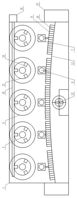
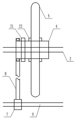
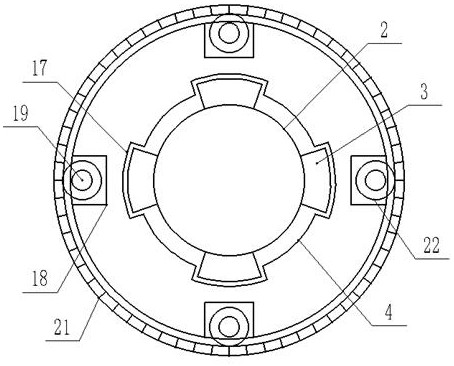
[0014] Example 1: see figure 1 , figure 2 , image 3 , Figure 4 , a post-processing equipment for the production and processing of brake pads provided by the present invention is now described, including a chassis 1, the upper end of the chassis 1 is designed to be open, and the upper end of the inner cavity of the chassis 1 is uniformly arranged with rotating shafts 2 along its length direction. , the outside of the rotating shaft 2 is uniformly fixed with guide blocks 3 with equal radians, the outside of the rotating shaft 2 is covered with a cylindrical displacement frame 4, and the external of the cylindrical displacement frame 4 is equipped with a grinding wheel 5, so The inner cavity of the cabinet 1 and the position directly below the rotating shaft 2 are provided with first screw rods 6, and the outside of the first screw rods 6 is covered with a first screw rod slider 7. The cylindrical displacement frame 4 One side of the average length direction is covered with...
Embodiment 2
[0015] Example 2: see figure 1 , the post-processing equipment for production and processing of brake pads provided by the present invention will now be described. The positions of the rotating shaft 2 are equipped with an annular transmission frame 13, and the ends of the rotating shaft 2 corresponding to the position of the annular transmission frame 13 are all movable and protrude through the inner end wall of the chassis 1, and its protruding end All parts are fixedly connected with the inner end wall of the annular transmission frame 13 through the connecting frame body, and the inner end wall of the annular transmission frame 13 is evenly provided with positioning connection cylinders 14 on the inner end wall of the annular transmission frame 13, and the positioning connection cylinders 14 are all arranged along the The radial direction of the inner end of the cross-section of the annular transmission frame 13 is set, and the outer end walls of the annular transmission f...
Embodiment 3
[0016] Embodiment 3: see figure 2 , image 3 , Figure 4 , the post-processing equipment for the production and processing of brake pads provided by the present invention will now be described. The guide blocks 3 are all arranged along the length direction of the rotating shaft 2, and the inner end walls of the cylindrical displacement frame 4 are all provided with equal arcs. Evenly have guide groove 17, described guide groove 17 all offers along described cylindrical displacement frame 4 length directions, and described guide groove 17 lengthwise both ends are all opening design, and described cylindrical displacement frame 4 outer end walls are all Respectively equal radians are evenly provided with bar-shaped grooves 18, and the bar-shaped grooves 18 are all opened along the length direction of the cylindrical displacement frame 4, and the two ends of the length direction of the bar-shaped grooves 18 are all non-opening designs. The second screw mandrel 19 is arranged i...
PUM
 Abstract
Description
Claims
Application Information
 - R&D
- Intellectual Property
- Life Sciences
- Materials
- Tech Scout
- Unparalleled Data Quality
- Higher Quality Content
- 60% Fewer Hallucinations
Browse by: Latest US Patents, China's latest patents, Technical Efficacy Thesaurus, Application Domain, Technology Topic, Popular Technical Reports.
© 2025 PatSnap. All rights reserved.Legal|Privacy policy|Modern Slavery Act Transparency Statement|Sitemap|About US| Contact US: help@patsnap.com


