Al technical title is built by PatSnap Al team. It summarizes the technical point description of the patent document.
A pipe cutting and functional technology, applied in applications, household utensils, tubular objects, etc., can solve problems such as easy stereotypes and inclined cut surfaces of PVC pipes
Inactive Publication Date: 2021-01-26
董渝郸
View PDF0 Cites 1 Cited by
Summary
Abstract
Description
Claims
Application Information
AI Technical Summary
This helps you quickly interpret patents by identifying the three key elements:
Problems solved by technology
Method used
Benefits of technology
Problems solved by technology
[0003] Since the PVC pipe with a thin diameter and long length is prone to be shaped when it is bent and stored for a long time, if the thin PVC pipe that has been bent for a long time is inserted into the clamping PVC pipe cutting machine for cutting, it will cause bending When the bending part of the shaped PVC pipe is squeezed into the cutting cavity, the cutting surface of the PVC pipe cut vertically downward by the cutter is inclined
Method used
Image
Click on the blue label to locate the original text in one second.
Reading with bidirectional positioning of images and text.
Examples
Embodiment 1
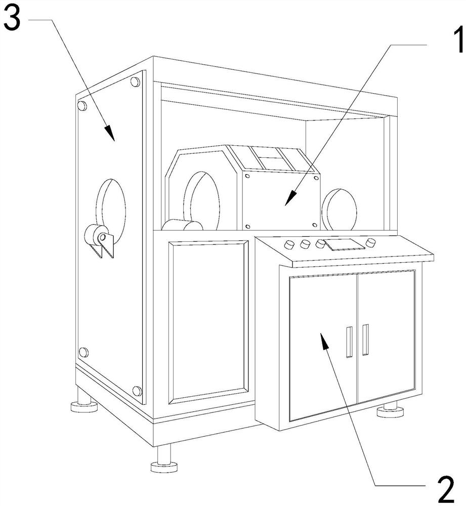
[0026] For example figure 1 -example Figure 5 Shown:
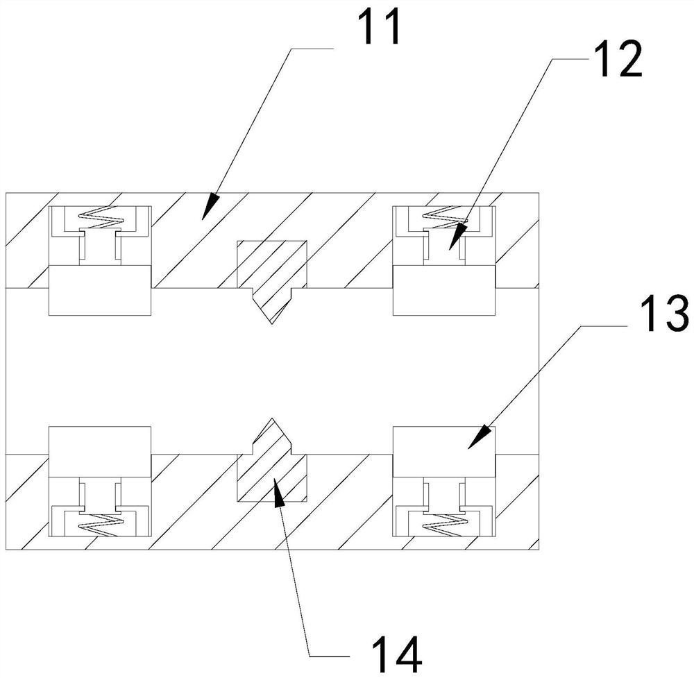
[0027] The present invention provides a PVC pipe cutting equipment with a clamping function. Its structure includes a cutting chamber 1, a control electric box 2, and a body 3. The control electric box 2 is installed on the right side of the body 3. The cutting chamber 1 is embedded and connected with the body 3; the cutting cavity 1 includes a casing 11, a booster frame 12, a clamping block 13, and a cutter 14, and the booster frame 12 is fixed between the inner side of the clamping block 13 and the shell 11 , the clamping block 13 is in clearance fit with the housing 11 , and the cutter 14 is installed in the middle of the inner wall of the housing 11 .
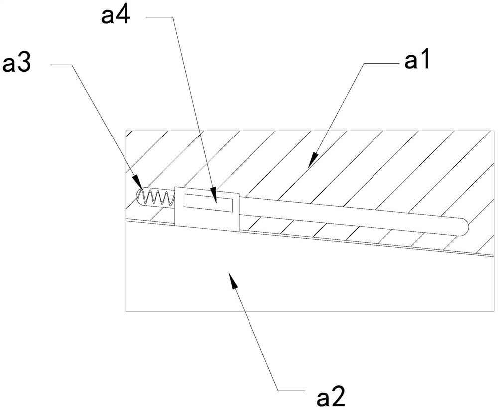
[0028] Wherein, the clamping block 13 includes an upper plate a1, a linkage plate a2, a pullback bar a3, and a transition piece a4. The linkage plate a2 is embedded in the bottom of the transition piece a4, and the pullback bar a3 is installed on Between the upper p...
Embodiment 2
[0034] For example Image 6 -example Figure 8 Shown:
[0035] Wherein, the cutter 14 includes a blade c1, a sleeve frame c2, a middle solid rod c3, and a pull-back strip c4. The blade c1 is movably engaged with the middle solid rod c3. The bottom is embedded and connected, and the pull-back strip c4 is installed on the upper end of the inner wall of the blade c1 and the upper surface of the middle solid rod c3. Through the force generated by the rotation of the mechanism, the blade c1 can be extended upward along the middle solid rod c3, Thus, the blade c1 can be used to cut the PVC pipe.
[0036] Wherein, the cover frame c2 includes a fitting block c21, a movable plate c22, and a frame c23, the fitting block c21 is embedded and fixed at the upper end of the movable plate c22, and the movable plate c22 is movably engaged with the bottom of the inner wall of the frame c23 The inner side of the frame c23 is provided with a hole through which the inside and the outside are tr...
PUM
Abstract
The invention discloses PVC pipe cutting equipment with a clamping function. The PVC pipe cutting equipment structurally comprises a cutting cavity, a control electric box and a machine body, whereinthe control electric box is installed at the right side position of the machine body, and the cutting cavity is fixedly connected with the machine body in an embedded mode. According to the PVC pipe cutting equipment with the clamping function, through conducting a PVC pipe into the interior of the cutting cavity, push-assisting frames can push contact plates on clamping blocks outwards to be attached to the outer surface of the PVC pipe; linkage plates can slide rightwards along upper placing plates through the continuous thrust generated by the push-assisting frames to the clamping blocks; the bending part of the PVC pipe can be pulled rightwards to be straightened through the linkage plates on the right clamping blocks; and blades can be pulled to contract inwards through pull-back strips, so that airflow generated by the contraction of the blades is attracted to movable plates through frames, then the movable plates slide towards the middle along the frames, the inner sides of attaching blocks are tightly attached to the vertical sides of the blades, and thus PVC plastic chips on the vertical sides are scraped off.
Description
technical field [0001] The invention relates to the field of pipe cutting, in particular to a PVC pipe cutting device with a clamping function. Background technique [0002] The clip-type PVC pipe cutting machine is mainly used for cutting PVC pipes into sections. The PVC pipe can be clamped by the fixed block inside the cutting chamber, and the cutting inside the cutting chamber can be made through the cooperation of the transmission device. The knife constantly cuts the PVC pipe, and is widely used in the PVC pipe manufacturing industry. Based on the above description, the inventors found that the existing equipment for cutting PVC pipes with a clamping function mainly has the following deficiencies, such as: [0003] Since the PVC pipe with a thin diameter and long length is prone to be shaped when it is bent and stored for a long time, if the thin PVC pipe that has been bent for a long time is inserted into the clamping PVC pipe cutting machine for cutting, it will cause...
Claims
Application Information
Patent Timeline
Application Date:The date an application was filed.
Publication Date:The date a patent or application was officially published.
First Publication Date:The earliest publication date of a patent with the same application number.
Issue Date:Publication date of the patent grant document.
PCT Entry Date:The Entry date of PCT National Phase.
Estimated Expiry Date:The statutory expiry date of a patent right according to the Patent Law, and it is the longest term of protection that the patent right can achieve without the termination of the patent right due to other reasons(Term extension factor has been taken into account ).
Invalid Date:Actual expiry date is based on effective date or publication date of legal transaction data of invalid patent.