Impurity removal system and method for shale gas wells
A technology for shale gas wells and shale gas, which is applied in the field of impurity removal systems for shale gas wells, and can solve the problems of inability to separate impurities from shale gas and poor effects
- Summary
- Abstract
- Description
- Claims
- Application Information
AI Technical Summary
Problems solved by technology
Method used
Image
Examples
Embodiment 1
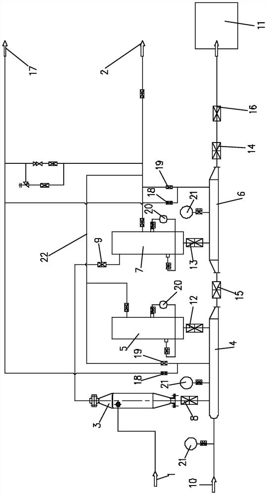
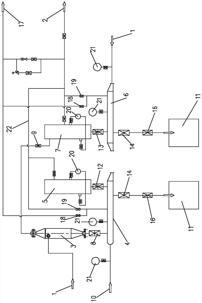
[0049] Such as figure 1 As shown, embodiment 1 provides a kind of impurity removal system for shale gas wells, embodiment 1 includes the inlet end 1 of shale gas, the output end 2 of shale gas and several connecting pipelines, and also includes cyclone separation Device 3, miscellaneous storage tank-4 and filter separator-5;
[0050] In this embodiment 1, there is at least one cyclone separator 3, and the cyclone separators 3 are sequentially labeled as 1, 2, 3...K...N, wherein K is any value from 1 to N, The inlet end of the first cyclone separator 3 communicates with the inlet port 1 through a pipeline, the inlet end of the Kth cyclone separator 3 communicates with the outlet end of the K-1 cyclone separator 3 through a pipeline, and the Nth cyclone separator 3 communicates with the outlet end of the K-1 cyclone separator 3 through a pipeline. The outlet end of the cyclone separator 3 communicates with the inlet end of the miscellaneous storage tank one 4 through a pipeline...
Embodiment 2
[0069] Embodiment 2 provides a method for removing impurities, based on the impurity removal system for shale gas wells described in Embodiment 1, including the process of removing impurities and cleaning impurities;
[0070] Specifically, the impurity removal system for shale gas wells applied in Example 2 can be set in the following manner:
[0071] Such as figure 1 As shown, the impurity removal system for shale gas wells includes cyclone separator 3, filter separator one 5, filter separator two 7, impurity collection device 11, impurity storage cylinder one 4, impurity storage cylinder two 6, air intake End 1, output end 2, fluid inlet end 10 and emptying end 17; Cyclone 3, filter separator one 5 and filter separator two 7 are all one, and the inlet end of cyclone separator 3 passes through pipeline and air intake Connected to terminal 1, the outlet end of cyclone separator 3 is connected to the inlet end of the miscellaneous storage tank-4 through a pipeline; the outlet ...
PUM
 Abstract
Description
Claims
Application Information
 - R&D
- Intellectual Property
- Life Sciences
- Materials
- Tech Scout
- Unparalleled Data Quality
- Higher Quality Content
- 60% Fewer Hallucinations
Browse by: Latest US Patents, China's latest patents, Technical Efficacy Thesaurus, Application Domain, Technology Topic, Popular Technical Reports.
© 2025 PatSnap. All rights reserved.Legal|Privacy policy|Modern Slavery Act Transparency Statement|Sitemap|About US| Contact US: help@patsnap.com


