
Sealing disc for vacuum sealing

A disk and vacuum technology, which is applied to the sealing of engines, valve devices, mechanical equipment, etc., can solve problems such as shortened service life, shear deformation, and damage to sealing surfaces

Pending Publication Date: 2021-01-26
SHANGHAI ADVANCED RES INST CHINESE ACADEMY OF SCI +2
View PDF0 Cites 2 Cited by
  • Summary
  • Abstract
  • Description
  • Claims
  • Application Information

AI Technical Summary

Problems solved by technology

However, it forms a sealing surface by abutting against each other between two metal layers, so the applied closing force needs to increase as the number of times the valve opens and closes, and its service life will be shortened accordingly
In addition, the dimensional change of the metal layer due to heating or cooling will cause relative motion between the two metal layers and cause shear deformation, thereby destroying the sealing surface

Method used


Image

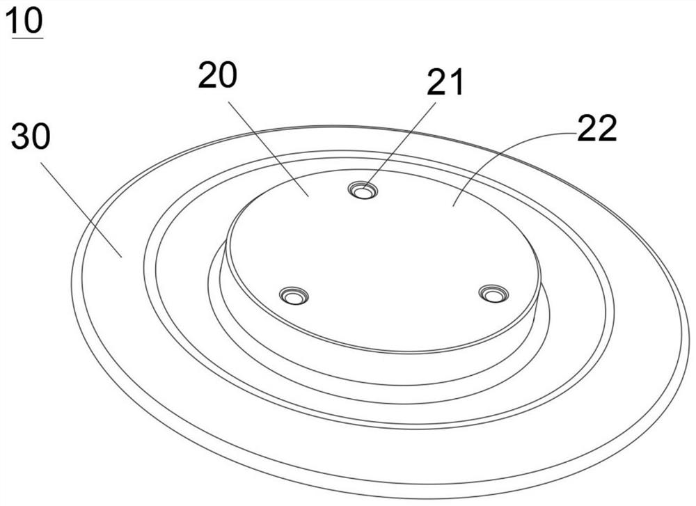
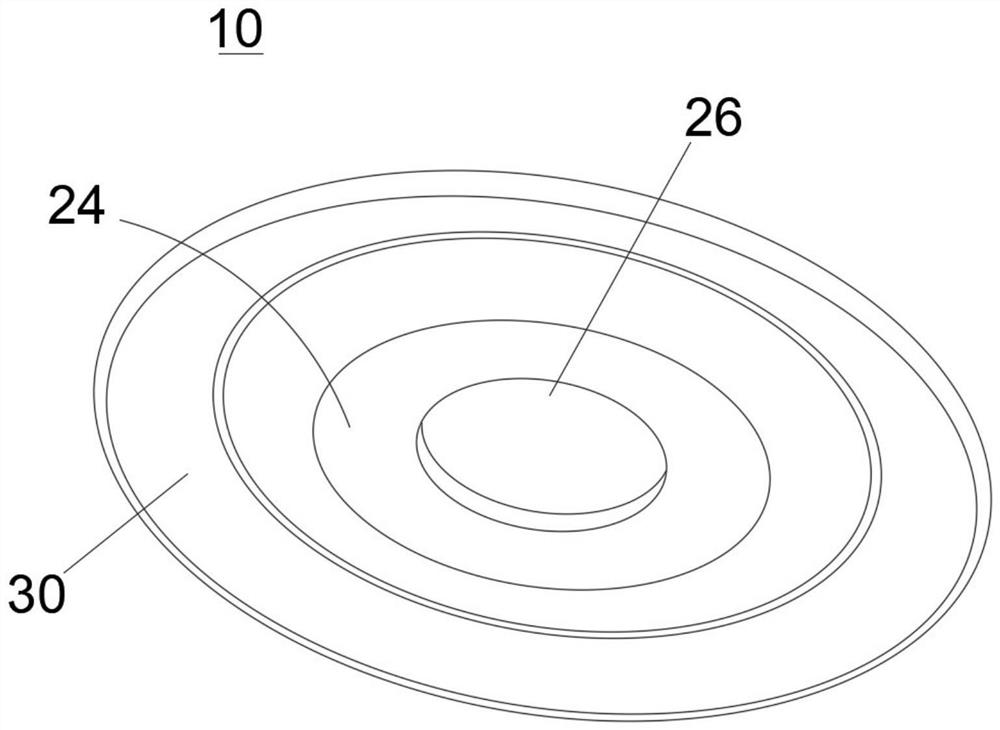
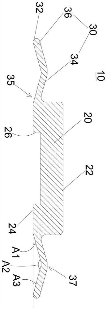
  • Sealing disc for vacuum sealing
  • Sealing disc for vacuum sealing
  • Sealing disc for vacuum sealing

Examples


Embodiment Construction

[0060] In order to facilitate the understanding of the technical features, content and advantages of the present invention and the effects that can be achieved, the present invention is hereby combined with the drawings and described in detail in the form of embodiments as follows, and the purposes of the drawings used therein are only For the purpose of illustrating and assisting the description, it may not be the true proportion and precise configuration of the present invention after implementation, so the scale and configuration relationship of the attached drawings should not be interpreted to limit the scope of rights of the present invention in actual implementation. In addition, for ease of understanding, the same components in the following embodiments are described with the same symbols.

[0061]The sealing disk for vacuum sealing of the present invention is suitable for reciprocatingly moving to the opening position or closing position of the vacuum valve to open or ...


PUM


Abstract

A sealing disc for vacuum sealing is suitable for moving to an opening position or a closing position in a reciprocating mode to open or seal a valve port of an all-metal valve. A first sealing face is formed on a sealing plate of the sealing disc, and the first sealing face of the the sealing disc directly abuts against a valve port of the all-metal vacuum valve at the closing position . By meansof compensation movement and adjustment movement when the sealing faces made of metal abut against each other, the vacuum sealing performance can be improved, and the service life can be prolonged.

Description

technical field [0001] The present invention relates to a sealing disc, in particular to a sealing disc for vacuum sealing. Background technique [0002] Most traditional vacuum valves use rubber-like elastic materials commonly known as O-rings as the sealing component between the valve plate and the valve body. Because the O-ring system achieves the required sealing effect through extrusion deformation, the O-ring is only suitable for valve bodies that do not require high sealing performance. Therefore, such sealing assemblies cannot be applied to high-vacuum systems, and cannot be applied to high-temperature environments. [0003] Although some high-vacuum systems use all-metal valves to replace rubber-like sealing components. However, the two metal layers contact each other to form a sealing surface, so the applied closing force needs to increase as the number of times the valve is opened and closed, and its service life will be shortened accordingly. In addition, the ...

Claims


Application Information

Patent Timeline
Patent Type & Authority Applications(China)
IPC IPC(8): F16K51/02F16J15/02
CPCF16K51/02F16J15/022F16K1/36F16K1/42
Inventor 胡晓赵烨梁张少辉寇崇善王衍圣王志纮许俊树林赐民蔡铭昇顾文伟
Owner SHANGHAI ADVANCED RES INST CHINESE ACADEMY OF SCI
Learn More