
Personnel transportation vehicle

A technology for transportation tools and personnel transportation, which is applied in the field of transportation vehicles for personnel transportation, and can solve the problems of spongy debris being thrown outwards, increased cleaning efforts, and easy aging and cracking of leather skins.

Inactive Publication Date: 2021-01-29
广州凯宇信息技术有限公司
View PDF0 Cites 0 Cited by
  • Summary
  • Abstract
  • Description
  • Claims
  • Application Information

AI Technical Summary

Problems solved by technology

[0003] Because the leather skin of the seat is prone to aging and cracking due to long-term use, and the backrest of the seat can be adjusted in angle, but when the staff resets the seat from the side when there is no one on the seat, the backrest of the seat will quickly move to the side. For front swing reset, if the backrest leather skin cracks for a long time, the internal sponge will become loose and broken after repeated friction with the personnel's back, it is easy to cause the sponge debris to be thrown out when the backrest is quickly reset, thus Circumstances that lead to increased cleaning efforts by staff

Method used


Image

  • Personnel transportation vehicle
  • Personnel transportation vehicle
  • Personnel transportation vehicle

Examples


Embodiment 1

[0026] For example figure 1 -example Figure 5 Shown:

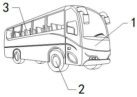
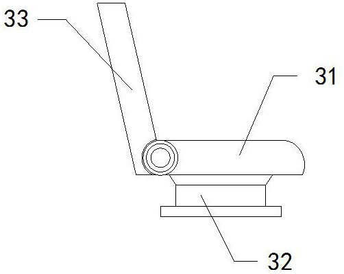
[0027] The present invention provides a means of transportation for transporting people. Its structure includes a passenger car 1, moving wheels 2, and seats 3. The moving wheels 2 are movably engaged with the bottom of the passenger car 1. The seat 3 is installed inside the passenger car 1. Position; the seat 3 includes a backrest 31, a support seat 32, and a cushion 33. The backrest 31 is embedded in the upper end of the support seat 32, and the seat cushion 33 is hinged to the left side of the backrest 31.

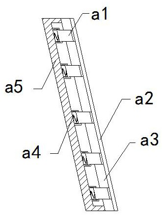
[0028] Wherein, the seat cushion 33 includes a telescopic plate a1, an outer skin a2, an inner cushion a3, an elastic strip a4, and an outer frame a5. In the inner position, the outer skin a2 is fixed on the right side of the inner pad a3, the elastic strip a4 is installed between the rear end of the outer skin a2 and the inner side of the outer frame a5, and five telescopic plates a1 are provided, and Evenly di...

Embodiment 2

[0034] For example Figure 6 -example Figure 8 Shown:

[0035] Wherein, the collection tank a14 includes a guide block c1, a bottom plate c2, and a contact plate c3, the guide block c1 and the contact plate c3 are an integrated structure, and the contact plate c3 is embedded and fixed on the inner side of the bottom plate c2 , the upper surface of the guide block c1 has an arc-shaped structure, and the sponge debris on the contact plate c3 can be guided into the inner position of the guide block c1 through the guide block c1.

[0036]Wherein, the guide block c1 includes a transition block c11, a clamping plate c12, a booster bar c13, a sleeve frame c14, and a deformable block c15. The transition block c11 is movably engaged with the sleeve frame c14, and the clamping plate c12 and The transition block c11 is an integrated structure, the booster bar c13 is installed between the transition block c11 and the inner side of the sleeve frame c14, the deformation block c15 is fixe...


PUM


Abstract

The invention discloses a personnel transportation vehicle. The vehicle structurally comprises a passenger car, moving wheels and a seat, wherein the moving wheels are movably clamped with the bottomof the passenger car, the seat is mounted in the passenger car, and when a person leaves the seat, a telescopic plate can be pushed outwards to extend outwards through an elastic strip, so that the telescopic plate can be matched with an outer skin and an inner pad to reset outwards; the elastic sheet pushes the stress plate outwards to conduct rapid reset, the air suction cavity in the stress plate can generate reverse airflow to absorb sponge chippings falling from the inner pad, the sponge chippings can be guided into the upper surface of the guide block through the contact plate, inward suction force is generated during reset of the stress plate, and therefore the sponge chippings can be sucked into the inner pad. According to the sponge scrap clamping device, sponge scraps can extrudethe space between the two clamping plates under the cooperation of airflow, so the clamping plates can contract towards the two sides under the cooperation of the transition blocks, and the two clamping plates can clamp the sponge scraps through reverse thrust generated by the boosting strips on the transition blocks.

Description

technical field [0001] The invention relates to the field of transportation, in particular to a transportation tool for transporting people. Background technique [0002] The passenger car is mainly used to transport people across distances. There are regular seats inside for people to use, so as to realize the purpose of transporting multiple people at the same time. It is a common device in life. Based on the above description The inventors found that the existing means of transportation for transporting people mainly has the following deficiencies, for example: [0003] The leather skin of the seat is prone to aging and cracking due to long-term use, and the backrest of the seat can be adjusted at an angle. For the front swing reset, if the backrest leather skin cracks for a long time, the internal sponge will become loose and broken after repeated friction with the back of the personnel, and it is easy to cause the sponge debris to be thrown out when the backrest is qui...

Claims


Application Information

Patent Timeline
Patent Type & Authority Applications(China)
IPC IPC(8): B60N2/64B60N2/70
CPCB60N2/64B60N2/7029
Inventor 陈晓璇
Owner 广州凯宇信息技术有限公司
Learn More