Full-section tunnel water and slag rapid discharging system and construction method

A construction method and full-section technology, applied in tunnels, drainage, tunnel lining, etc., can solve the problems of low efficiency and high cost, and achieve the effect of avoiding blockage and efficient and convenient cleaning.

Active Publication Date: 2021-01-29
CHINA RAILWAY CONSTR BRIDGE ENG BUREAU GRP OF THE FIFTH ENG +2
View PDF5 Cites 0 Cited by
  • Summary
  • Abstract
  • Description
  • Claims
  • Application Information

AI Technical Summary

Problems solved by technology

However, for the small tunnel slag generated during the subsequent secondary lining construction and the construction of the inverted arch filling layer and scattered on the top of the inverted arch filling layer, the cost of using large machinery to transport and discharge the slag is too high, and the efficiency of manual cleaning is low. Very low, thereby delaying the overall tunnel construction process

Method used


Image

  • Full-section tunnel water and slag rapid discharging system and construction method
  • Full-section tunnel water and slag rapid discharging system and construction method

Examples


Embodiment 1

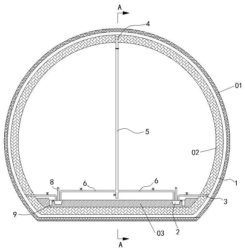
[0030] A full-section tunnel rapid drainage and slag discharge system in this embodiment, such as figure 1 As shown, the inside of the tunnel is provided with primary support 01 and secondary lining 02 sequentially from the outside to the inside, and the top of the inverted arch at the bottom of the tunnel is provided with an inverted arch filling layer 03. The rapid drainage and slag discharge system includes several The aqueduct 1 is linearly arranged between the primary support 01 and the secondary lining 02 in the length direction of the tunnel, and side drains 2 are arranged on both sides of the inverted arch filling layer 03 along the length direction of the tunnel. The aqueduct 1 is close to Inverted arch filling layer 03 is linearly provided along the length direction of the tunnel with a number of side drainage pipes 3 connected to the aqueduct 1 and leading to the side drainage ditch 2; 4. The water outlet end of the middle drainage pipe 4 is connected to the middle ...

Embodiment 2

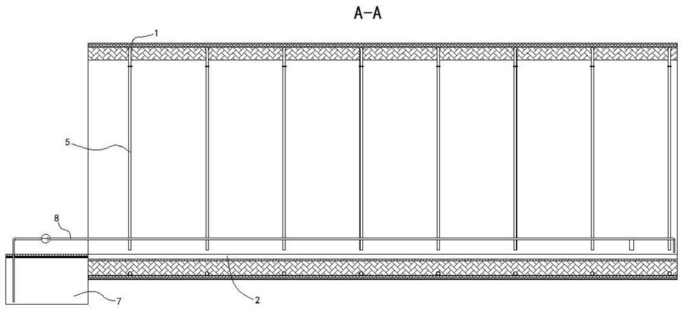
[0034] This embodiment is further optimized on the basis of embodiment 1, such as figure 1 and figure 2 As shown, the end of the side drainage ditch 2 extending to the outside of the tunnel is provided with a sump 7, the sump 7 is provided with a return pipe 8, and the return end of the return pipe 8 extends to the inner side of the tunnel close to At the palm face and leading to the side drain 2.

[0035] The accumulated water passing through the side drainage ditch 2 finally flows to the sump 7 outside the tunnel for temporary storage. The accumulated water is suctioned and returned to the side drain 2 near the tunnel face, and the returned accumulated water washes the tunnel slag inside the side drain 2 for a second time to prevent the tunnel slag from being trapped in the side drain 2 The side drain 2 is clogged due to heavy buildup.

[0036]Further, the top of the sump 7 is provided with a multi-layer grid, through which the tunnel slag in the accumulated water is fil...

Embodiment 3

[0039] This embodiment is further optimized on the basis of above-mentioned embodiment 1 or 2, such as figure 1 As shown, it also includes an auxiliary drainage ditch 9 arranged on one side of the side drainage ditch 2 , and the side of the auxiliary drainage ditch 9 close to the side drainage ditch 2 is linearly provided with a number of drain holes communicating with the side drainage ditch 2 .

[0040] The top of the auxiliary drainage ditch 9 is connected to the top of the side drainage ditch 2 through the drainage hole. When the water level in the side drainage ditch 2 exceeds the height of the drainage hole, the accumulated water in the side drainage ditch 2 enters the auxiliary drainage through the drainage hole ditch 9, avoiding the overflow of accumulated water in the side gutter 2.

[0041] At the same time, by monitoring the water output of the auxiliary drainage ditch 9, when the water output in the auxiliary drainage ditch 9 is large, it means that there is more t...


PUM


Abstract

The invention discloses a full-section tunnel water and slag rapid discharging system. Rapid water and slag discharging is conducted on the interior of a tunnel. Meanwhile, the invention further discloses a full-section tunnel water and slag rapid discharging construction method. Flowing in a water guide pipe is controlled, tunnel slag on an inverted arch filling layer is flushed to side drainageditches through accumulated water, and rapid water and slag discharging is conducted through the side drainage ditches. Tunnel slag accumulation or water accumulation in the tunnel is effectively avoided, and therefore the tunnel construction efficiency is improved.

Description

technical field [0001] The invention belongs to the technical field of tunnel construction, and in particular relates to a fast drainage and slag discharge system for a full-section tunnel and a construction method. Background technique [0002] With the development of my country's transportation construction, more and more tunnels have been built. With the improvement of traffic planning requirements, the tunnel sections have gradually become larger and larger. Now for large-section tunnels, smooth blasting is generally used for one-time forming excavation. Then the initial support and secondary lining are applied, and the large tunnel slag generated during blasting can be quickly transported out of the tunnel by excavators and other machinery. However, for the small tunnel slag generated during the subsequent secondary lining construction and the construction of the inverted arch filling layer and scattered on the top of the inverted arch filling layer, the cost of using la...

Claims


Application Information

Patent Timeline
Patent Type & Authority Applications(China)
IPC IPC(8): E21F16/02E21D11/38
CPCE21F16/02E21D11/38
Inventor 张玉伟何十美郭建强周文宋战平田小旭马天昌田松
Owner CHINA RAILWAY CONSTR BRIDGE ENG BUREAU GRP OF THE FIFTH ENG
Why Eureka
Try Eureka