


Quick Research
Generate reliable direction feasibility study reports for your R&D in just a few steps.

Technical Q&A
Discover and master advanced knowledge NOW. Basics, ideas, possibilities, all at once.

Find Solutions
As an expert in R&D theories, this can generate solutions to your technical problems instantly.

Evaluate Feasibility
Analyze your overall solution with one click, know your potential R&D risks in advance.

Monitor Landscape
Get weekly tech updates, stay abreast of the latest tech innovations and key insights.
Antiferroelectric liquid crystal cell
A liquid crystal cell, antiferroelectric technology, applied in nonlinear optics, instruments, optics, etc., can solve the problem of unsatisfactory light transmission rate
- Summary
- Abstract
- Description
- Claims
- Application Information
AI Technical Summary
Problems solved by technology
Method used
Image

Examples
Embodiment
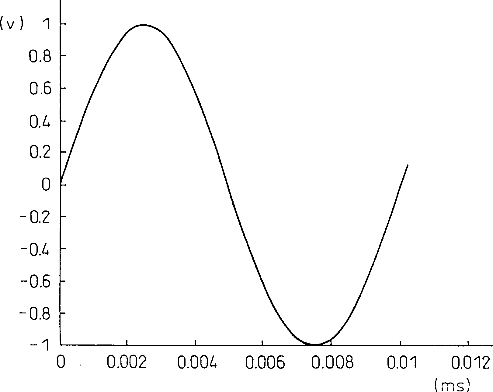
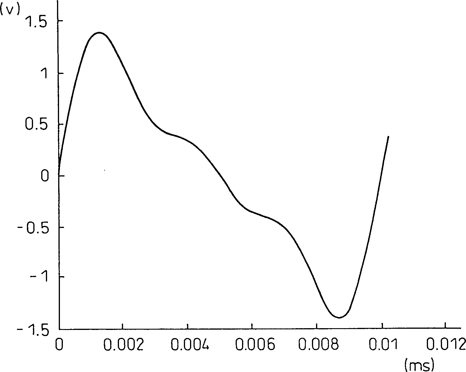
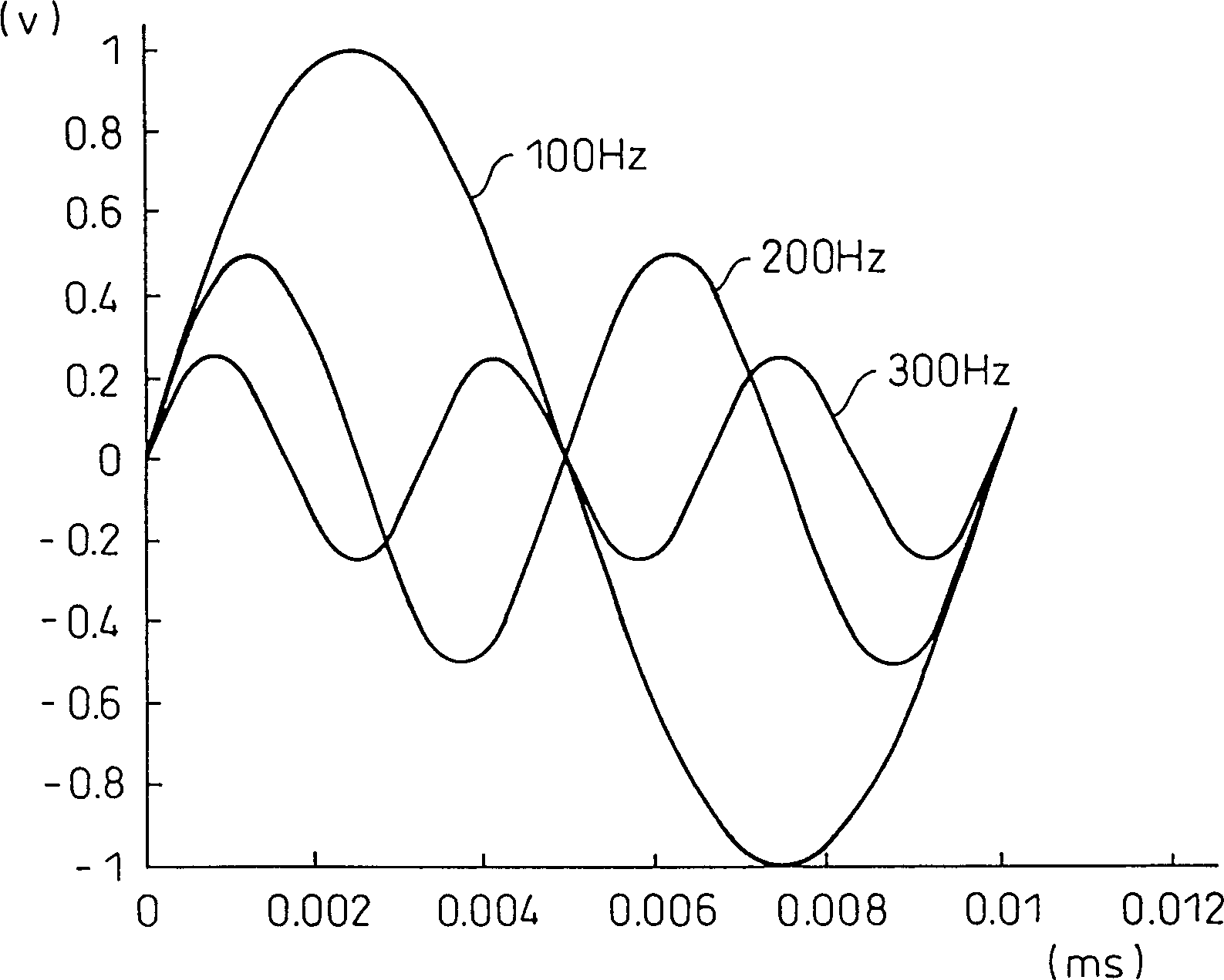
[0043] In order to apply a sinusoidal voltage of a single frequency on the antiferroelectric liquid crystal cell and measure the fundamental and harmonic components of the output voltage at this time, prepare Figure 7 circuit as shown. for the preparation of Figure 7 In the liquid crystal cell in the paper, a polyimide with a thickness of 300 angstroms was deposited as an alignment film on each of the two glass plates by the spin coating method, and then the two substrates were bonded together. Thereafter, the liquid crystal cell is preheated to about 100°C, and the AFLC material is injected into the liquid crystal cell by vacuum injection technology.
[0044] After the liquid crystal thickness is set to 1.5μm and the optical path length is about 220nm, press Figure 7 Set up the liquid crystal cell as shown in , and measure the dielectric constant. exist Figure 7 Among them, reference number 1 is a power supply with a reference frequency, and the liquid crystal cell 2 ...
PUM
 Abstract
Description
Claims
Application Information
 - R&D Engineer
- R&D Manager
- IP Professional
- Industry Leading Data Capabilities
- Powerful AI technology
- Patent DNA Extraction
Browse by: Latest US Patents, China's latest patents, Technical Efficacy Thesaurus, Application Domain, Technology Topic, Popular Technical Reports.
© 2024 PatSnap. All rights reserved.Legal|Privacy policy|Modern Slavery Act Transparency Statement|Sitemap|About US| Contact US: help@patsnap.com